Camera module having a side actuator

A technology for an actuator and a camera, which is applied to cameras, focusing devices of cameras, focusing devices of projectors, etc., can solve problems such as influence, and achieve the effect of reducing the influence of magnetic fields

Inactive Publication Date: 2017-08-01
MDPULSE
View PDF5 Cites 0 Cited by
  • Summary
  • Abstract
  • Description
  • Claims
  • Application Information

AI Technical Summary

Problems solved by technology

[0006] The latch type solenoid type actuator has been disclosed in Korean Registered Patent Publication No. 0649490, but there is no solution to avoid the influence of the magnetic field generated in the coil on other components

Method used


Image

  • Camera module having a side actuator
  • Camera module having a side actuator
  • Camera module having a side actuator

Examples


Embodiment Construction

[0026] Embodiments applicable to the present invention will be described in detail below in conjunction with the accompanying drawings. In the process, for clarity and convenience of description, the size and shape of the components shown in the drawings may be exaggerated. In addition, the terms specifically defined in consideration of the constitution and operation of the present invention may vary depending on the user's or applicator's intention or practice. The definitions of these terms should be based on the entire content of this specification.

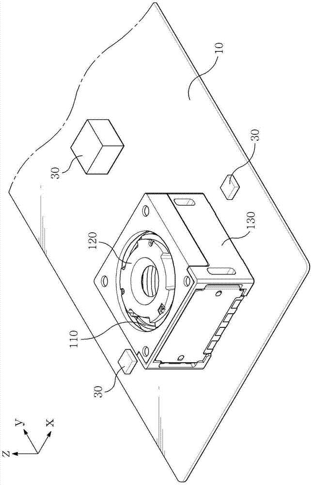
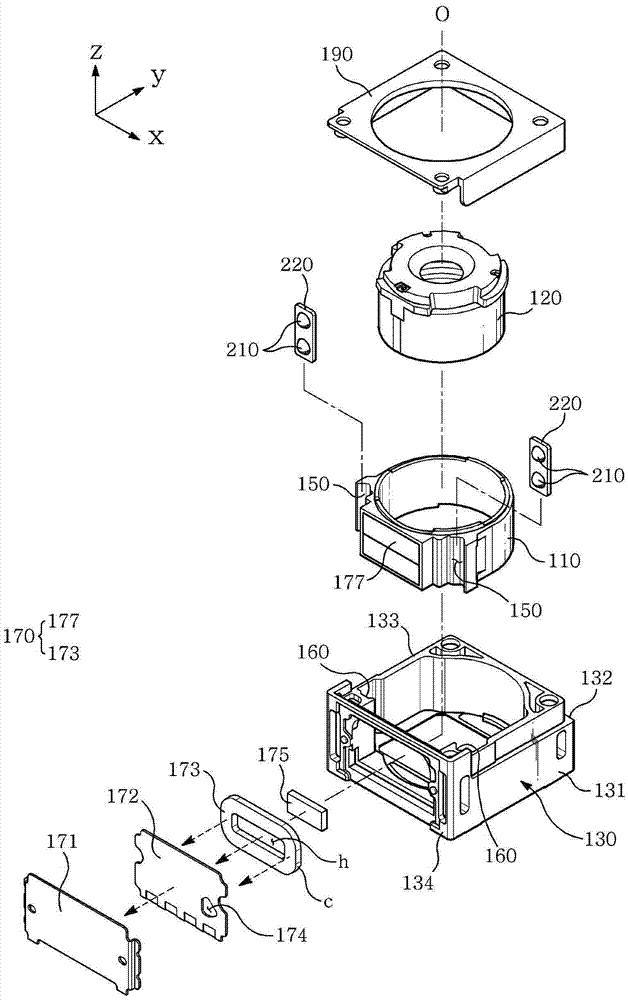
[0027] figure 1 is a perspective view of a camera module to which the present invention is applied, figure 2 It is an exploded perspective view of a camera module to which the present invention is applied.

[0028] The illustrated camera module includes: a moving part 110 , a fixed part 130 , a side actuator 170 , a ball 210 , and a coil.

[0029] A lens (not shown) may be fixedly installed in the moving part 110 . When ...


PUM


Abstract

A camera module is provided, comprising: a mover mounted with a lens; a stator supporting the mover to an optical direction of the lens; a side actuator mounted with a coil and a magnet moving the mover to the optical direction relative to the stator; a ball interposed between the mover and the stator; and coils, each coil provided at the mover and the stator to guide a linear travel of the ball, wherein the side actuator is lopsidedly arranged at each one side of the stator and the mover.

Description

technical field [0001] The present invention relates to a camera module (CAMERA MODULE) equipped with a coil for providing a driving force required for relative movement of a moving part and a fixed part. Background technique [0002] With the continuous improvement of mobile phone pixels, the focus of competition in the mobile phone industry market has gradually evolved into camera control technology that can achieve high-definition image quality. A compact digital camera module with high-resolution features needs to be equipped with an auto-focusing function in order to achieve high-definition image quality despite its small size. [0003] At present, the autofocus function is generally applicable to traditional digital cameras, but there are still many difficulties in realizing the compact digital camera modules whose length and width are reduced to within tens of mm. [0004] In order to realize the autofocus function in a compact camera module, an innovative modificati...

Claims


Application Information

Patent Timeline
Patent Type & Authority Applications(China)
IPC IPC(8): G03B13/36G02B7/28
CPCG02B7/282G03B13/36G03B3/10H02K41/0356G03B2205/0069G01R33/072G02B7/09G02B13/001H02K41/0354
Inventor 金镇国
Owner MDPULSE
Why Eureka
Try Eureka