High-dehumidification electric generator set box body

A technology for generating sets and cabinets, which is applied in the direction of refrigerators, compressors, and irreversible cycle compressors, etc. It can solve problems such as endangering the safe operation of equipment, rising working environment temperature, and unsuitable personnel to operate, and achieves a wide range of air supply , high heat dissipation efficiency, and the effect of improving the service life

Active Publication Date: 2014-01-29
FUJIAN RUNDA POWER MACHINERY CO LTD
View PDF7 Cites 10 Cited by
  • Summary
  • Abstract
  • Description
  • Claims
  • Application Information

AI Technical Summary

Problems solved by technology

Existing high dehumidification generating set cabinets usually only consider the problem of ventilation and cooling, often ignoring the importance of humidity control, especially in the case of high humidity in the working environment, the cold air entering the generator cabinet contains more A lot of water absorbs the heat of the generator set to form hot and humid air, so that the generator set and other electrical equipment in the generator box are always in a high-temperature and high-humidity environment, which accelerates the aging and failure frequency of the equipment, and once the temperature in the generator box Changes, hot and humid air will quickly condense on the generator set and other electrical equipment, resulting in equipment short circuit, insulation performance degradation, rust and aging, etc., seriously endangering the safe operation of equipment
In addition, the existing ventilation and cooling system of the high dehumidification generator box usually discharges the hot air after heat dissipation directly into the working environment, resulting in an increase in the temperature of the working environment, which is not suitable for personnel to operate

Method used


Image

  • High-dehumidification electric generator set box body

Examples


Embodiment Construction

[0023] In order to describe the technical content, structural features, achieved goals and effects of the present invention in detail, the following will be described in detail in conjunction with the embodiments and accompanying drawings.

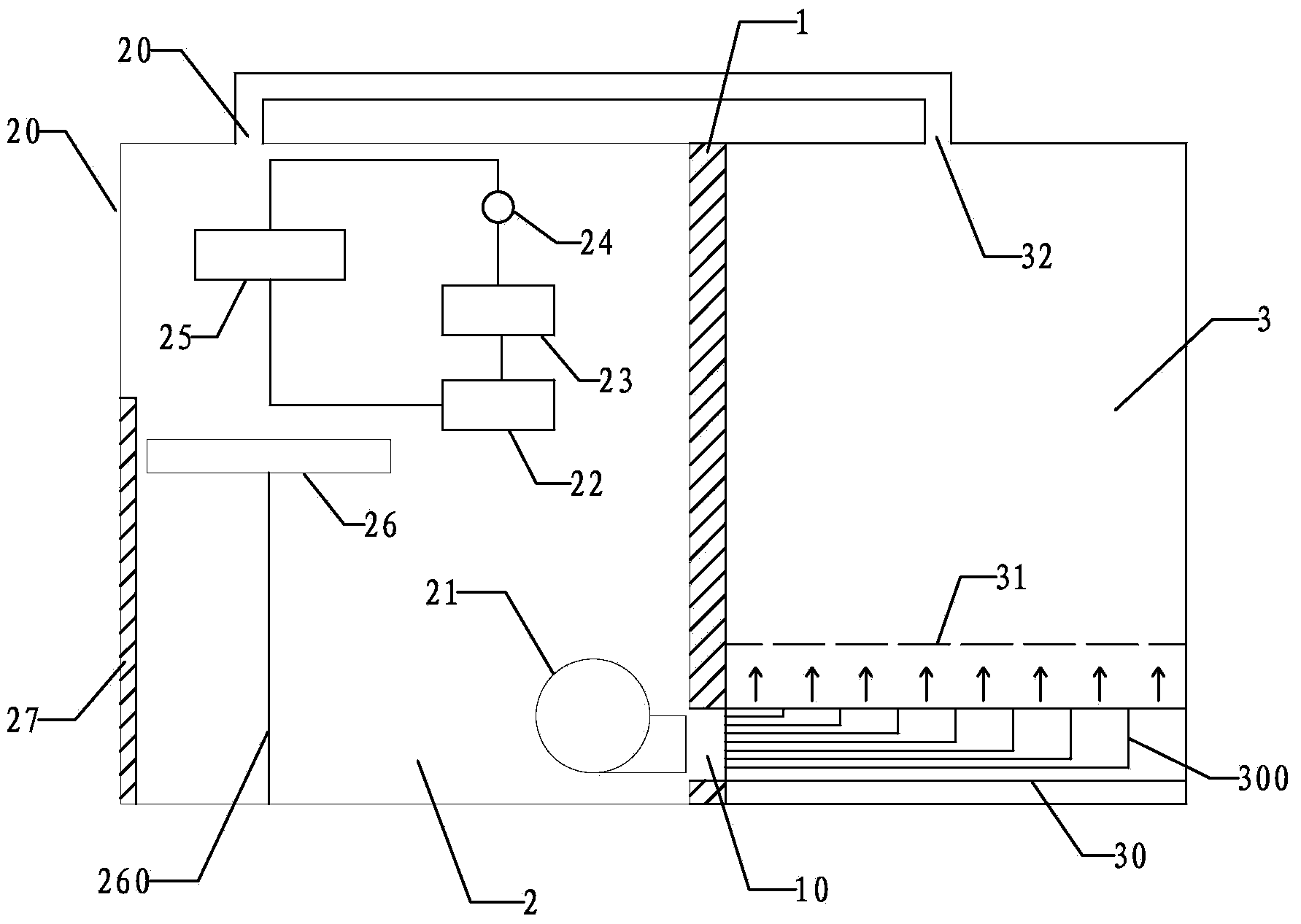
[0024] see figure 1 As shown, the inner chamber of the high dehumidification generator set box of this embodiment is divided into an air intake chamber 2 and a generator set chamber 3 by a partition 1, and an air inlet 20 is opened on the top of the air intake chamber 2 , the top of the generator set chamber 3 is provided with an exhaust port 32, the air inlet 20 is connected to the exhaust port 32 through a pipeline, and the bottom of the partition 1 is provided with an air vent 10;

[0025] The air intake chamber 2 is provided with a refrigerating device, a drainage device and a fan 21, and the refrigerating device includes a compressor 22, a condenser 23, an expansion valve 24 and an evaporator 25 which are sequentially connected to for...


PUM


Abstract

The invention relates to a high-dehumidification electric generator set box body. An inner cavity of the box body is divided into a gas inlet cavity and an electric generator set cavity through a partition plate, a refrigeration device, a water receiving and draining device and a draught fan are arranged in the gas inlet cavity, and an air duct and a mesh-shaped partition plate used for installation of an electric generator set are arranged in the electric generator set cavity. The high-dehumidification electric generator set box body has the excellent dehumidification performance, the excellent heat dissipation performance and the excellent heat insulation performance at the same time, can well meet the requirement for temperature and humidity control of a device and the requirement of personnel for the operating environment, ensures that the electric generator set and other electrical equipment in the high-dehumidification electric generator set box body safely and stably run, prolongs the service life of the device, is particularly suitable for the working environment with the high temperature and the high humidity, and has quite wide market application prospects.

Description

technical field [0001] The invention relates to a box body of a high dehumidification generator set. Background technique [0002] The generator set must maintain a certain temperature and humidity state in order to ensure safe and normal operation. The heat dissipation of the generator set is large during operation, and a reasonable ventilation and cooling scheme needs to be designed to ensure that the waste heat can be removed in time to avoid the temperature exceeding the allowable value. Existing high dehumidification generating set cabinets usually only consider the problem of ventilation and cooling, often ignoring the importance of humidity control, especially in the case of high humidity in the working environment, the cold air entering the generator cabinet contains more A lot of water absorbs the heat of the generator set to form hot and humid air, so that the generator set and other electrical equipment in the generator box are always in a high-temperature and hi...

Claims


Application Information

Patent Timeline
Patent Type & Authority Applications(China)
IPC IPC(8): H05K7/20F25B1/00
Inventor 沈廷尧沈庭光刘建辉
Owner FUJIAN RUNDA POWER MACHINERY CO LTD
Why Eureka
Try Eureka