Automatic cutting equipment for bar type material continuous discharging system

A technology of automatic cutting and discharging system, applied in metal processing and other directions, can solve the problems of difficult adjustment of manual operation process, unfavorable industrial expansion, failure to meet positioning requirements, etc., to improve the low efficiency of manual operation and the automation of equipment. High level, easy maintenance and adjustment

Active Publication Date: 2014-02-05
吴德会
View PDF6 Cites 10 Cited by
  • Summary
  • Abstract
  • Description
  • Claims
  • Application Information

AI Technical Summary

Problems solved by technology

This method has high labor intensity, high labor cost, poor cutting accuracy, and low efficiency; at the same time, the manual placement accuracy is low, which often fails to meet the positioning requirements of the subsequent automation process, which is not conducive to industrial expansion
Moreover, it is not easy to adjust the manual operation process. In the market with diversified products, the competitiveness of enterprises is low.

Method used


Image

  • Automatic cutting equipment for bar type material continuous discharging system
  • Automatic cutting equipment for bar type material continuous discharging system
  • Automatic cutting equipment for bar type material continuous discharging system

Examples


Embodiment 1

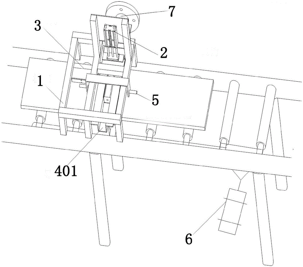
[0031] as attached figure 1 As shown, the present invention is mainly made of frame 1, automatic cutting mechanism 2, support mechanism 3, guide groove, position sensor 5, transmission mechanism 6 and electric control system. The frame is fixed on the transmission mechanism or on the continuous discharge system, and is mainly used to install the dynamic cutting mechanism, support mechanism, guide groove and position sensor; the automatic cutting mechanism is fixed on the frame and is located in the discharge of the continuous discharge system. Port 7 is used to automatically cut off the rod-shaped material at the discharge port; the support mechanism is located in front of the discharge port and below the automatic cutting mechanism, and is used to support and blank the material 8 at the discharge port; the guide groove is fixed on the support On the frame above the mechanism, it is used to guide the rod-shaped material at the discharge port; the position sensor is fixed at t...

Embodiment 2

[0043] An automatic cutting method for an automatic cutting device of a continuous discharge system for rod-shaped materials according to the present invention comprises the following steps:

[0044] 1) In the initial state, the cutter of the automatic cutting mechanism is in the incision position, the support plate of the support mechanism is in the support position, and the continuous carbon rod processed by the carbon rod extrusion molding equipment advances along the guide groove on the support mechanism;

[0045] 2) The position sensor detects the length of the material. When the front end of the material reaches the set point, the position sensor outputs a signal to the input port of the logic control unit;

[0046] 3) The logic control unit issues instructions to the automatic cutting mechanism, and the cutting cylinder drives the cutter to perform external or internal cutting actions, thereby cutting off the material;

[0047] 4) After the material is cut off, the supp...


PUM


Abstract

The invention discloses automatic cutting equipment for a bar type material continuous discharging system. The automatic cutting equipment is mainly used for the bar type material continuous discharging system and is structurally characterized by being arranged at the material outlet of the bar type material continuous discharging system, wherein a supporting mechanism is arranged in front of the material outlet, and a guide slot is fixedly arranged above the supporting mechanism; a position sensor is arranged at the periphery of the guide slot; a transmission mechanism is positioned below the supporting mechanism; a material moves forward along the guide slot on the supporting mechanism by virtue of the material outlet; when the material reaches at a set length, the position sensor sends out an effective signal, an electrical control system drives the automatic cutting mechanism to cut off the material; meanwhile, supporting plates on the supporting mechanism move back to perform blanking, so that the material is regularly discharged on a blanking plate, and the transmission mechanism drives the blanking plate to discharge the material, by parity of reasoning, so that the automatic cutting and discharging of the material can be realized. By utilizing the high degree of automation and low manufacturing cost of the equipment, the defects of low efficiency and low cutting precision of existing manual operation can be improved.

Description

technical field [0001] The invention relates to an automatic cutting device for a continuous discharging system of rod-shaped materials. Background technique [0002] Existing production often involves a continuous discharge system for stick-shaped materials, such as production equipment for charcoal sticks, popcorn sticks, and vermicelli. When this type of system works, it often discharges continuously, forming a long rod-shaped material. However, due to the limitation of actual space, subsequent processing and other conditions, it is necessary to realize automatic cutting and neat arrangement for the implementation of subsequent automatic processes. The traditional cutting method mainly adopts manual operation method. This method has high labor intensity, high labor cost, poor cutting accuracy, and low efficiency. At the same time, the manual placement accuracy is low, which often fails to meet the positioning requirements of the subsequent automation process, which is n...

Claims


Application Information

Patent Timeline
Patent Type & Authority Applications(China)
IPC IPC(8): B26D1/06B26D5/12B26D7/32B26D7/06B26D7/28
Inventor 吴德会孙宝康房未翼柳振凉
Owner 吴德会
Why Eureka
Try Eureka