Collecting device for stamped radiating fins

A collection device and heat dissipation fin technology, which is applied to the transmission device, transportation and packaging, multi-axis trolley, etc., can solve the problems of unable to improve production efficiency, single function, and large labor consumption, so as to reduce the labor load of workers and control Simple and accurate, the effect of improving work efficiency

Active Publication Date: 2014-02-05
OMS MASCH CO LTD
View PDF7 Cites 9 Cited by
  • Summary
  • Abstract
  • Description
  • Claims
  • Application Information

AI Technical Summary

Problems solved by technology

On the one hand, this retrieving process requires a lot of labor, and the production efficiency is low, which increases the cost; on the other hand, it is easy to cause damage to the cooling fins during the handling process, which affects the next processing.
[0004] In addition, due to the single structure and function of the collecting device, the cooling fins need to be taken out before the next collection can be carried out after the cooling fins are filled with the receiving needles. The processing flexibility is limited, and the material taking process takes a certain amount of time. lead to the inability to improve production efficiency

Method used


Image

  • Collecting device for stamped radiating fins
  • Collecting device for stamped radiating fins
  • Collecting device for stamped radiating fins

Examples


Embodiment Construction

[0041] The present invention will be further described in detail below in conjunction with the accompanying drawings and specific embodiments. It is necessary to point out that the following embodiments are only used to further illustrate the present invention, and should not be interpreted as limiting the protection scope of the present invention. Those of ordinary skill in the art can make some non-essential changes to the following embodiments according to the essence of the present invention. Improvements and adjustments. In addition, the technical features involved in the various embodiments of the present invention described below can be combined with each other as long as there is no conflict between the other features.

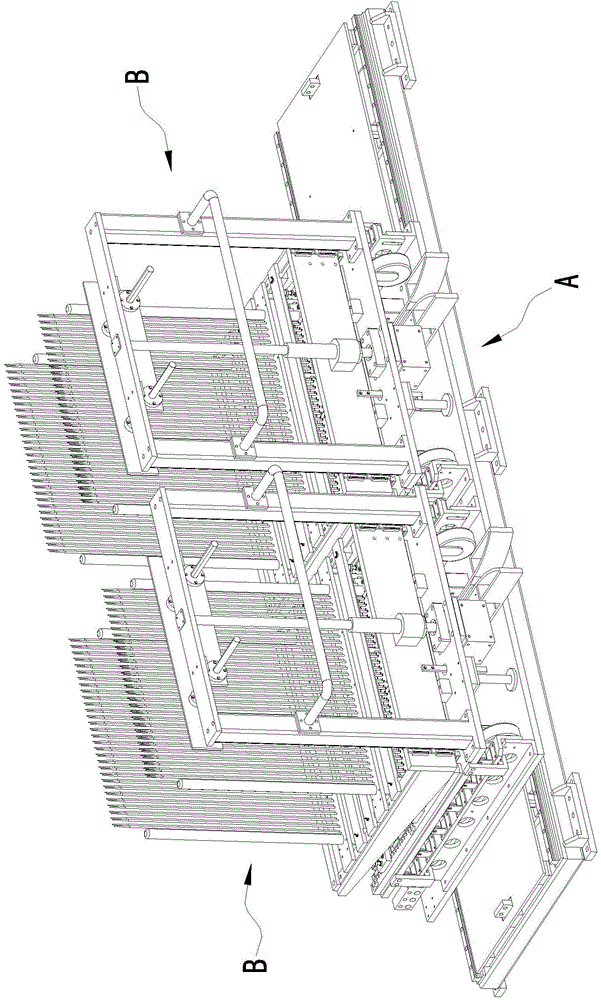
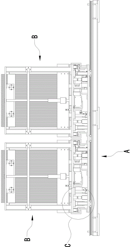
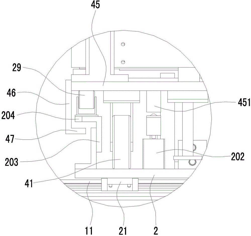
[0042] Such as Figure 1 to Figure 20 As shown in Fig. 1, a collecting device after stamping of heat dissipation fins, including workbench A and collecting trolley B;

[0043] The workbench A includes a base 1 and a flat plate 2 arranged on the base ...


PUM


Abstract

The invention relates to a collecting device for stamped radiating fins. The collecting device comprises a workbench and collecting trolleys, wherein the workbench comprises a base and a flat plate which is arranged on the base and can be used for allowing the collecting trolleys to be parked; the flat plate can be arranged on the base in a sliding way; the base is provided with a trolley switching mechanism for driving the flat plate to slide; at least two parking spaces are arranged on the flat plate at certain intervals along the sliding direction of the flat plate; each parking lot can be used for allowing one collecting trolley to be parked. According to the collecting device, after receiving pins of one collecting trolley are full of radiating fins, the flat plate slides to drive the no-load trolley on the other parking spaces to move below an adsorption device for receiving, the receiving trolley which is full of the radiating fins is driven away from the adsorption device, and workers pull the collecting trolley which is full of the radiating fins out of the flat plate to another machining place for unloading, so that the carrying distance of the workers can be reduced, and a large amount of labor force is saved; on the other hand, the trolley switching time is short, next collection can be performed without taking the radiating fins out, so that the collecting device has the advantages of high machining flexibility and high working efficiency.

Description

[0001] Field: [0002] The invention relates to a material collecting device after heat dissipation fins are stamped. Background technique: [0003] The raw material of heat exchanger fins for air conditioners is aluminum foil coil material, which is rolled out on the spreading roller and sent to the punching machine for punching during production. After the fins are punched and formed, they are sent to the material collection device by the adsorption device. The material collection device is equipped with a material receiving needle. In the existing retrieving process, workers generally take out a large stack of cooling fins directly from the receiving needle and then transport them to another processing place for further processing such as pipe threading and expansion. On the one hand, this retrieving process requires a lot of labor, and the production efficiency is low, which increases the cost; on the other hand, it is easy to cause damage to the cooling fins during the h...

Claims


Application Information

Patent Timeline
Patent Type & Authority Applications(China)
IPC IPC(8): B26D7/32B62B3/02B62B3/10F16H37/12
Inventor 龙晓斌
Owner OMS MASCH CO LTD
Why Eureka
Try Eureka