

Plastic pipe interface device
A technology of interface equipment and plastic pipes, which is applied in the direction of mechanical equipment, pipeline connection layout, pipes/pipe joints/fittings, etc., can solve the problems of plastic pipe joint failure, joint falling off, and small axial pressure resistance and impact force at the butt joint, etc. Achieve the effects of easy use and maintenance, guaranteed performance, and firm interface
- Summary
- Abstract
- Description
- Claims
- Application Information
AI Technical Summary
Problems solved by technology
Method used
Image

Examples
Embodiment Construction
[0026] The present invention will be further described below in conjunction with the accompanying drawings and embodiments. However, the uses and purposes of these exemplary embodiments are only used to illustrate the present invention, and do not constitute any form of limitation to the actual protection scope of the present invention, nor limit the protection scope of the present invention thereto.
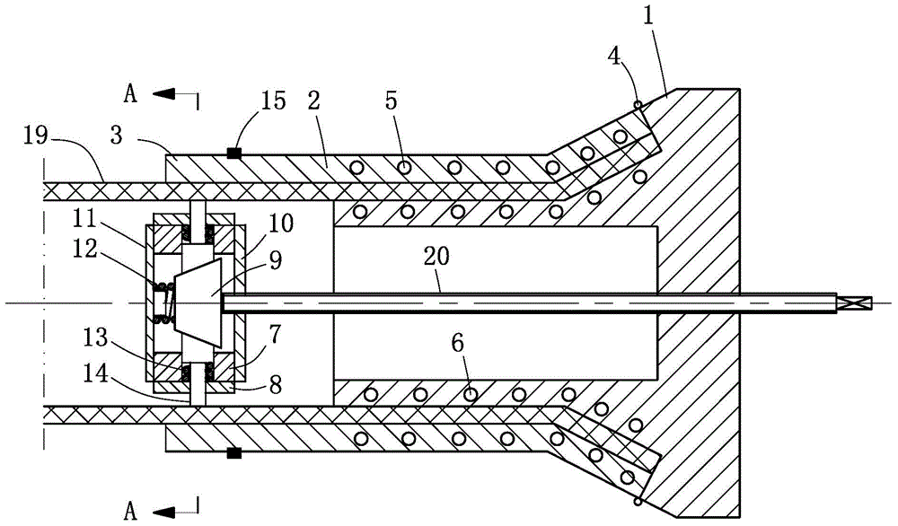
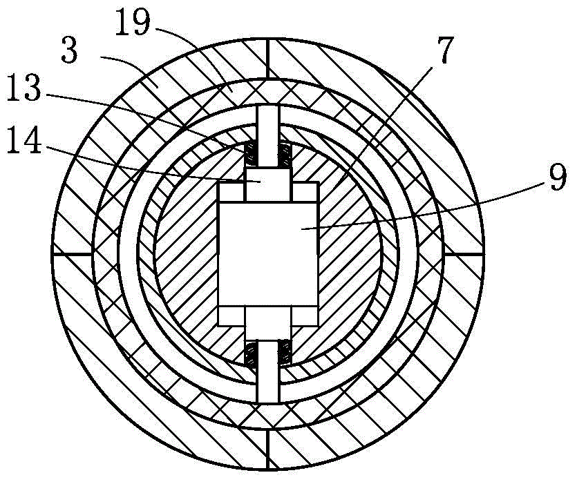
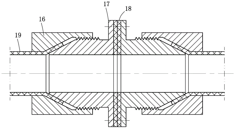
[0027] Such as figure 1 , figure 2 and image 3 Commonly shown in, the present invention provides a plastic pipe interface device, the plastic pipe interface equipment mainly includes a flaring device for flaring the end of the plastic pipe 19 into a bell mouth and for tightening and connecting the bell mouth The connecting device together, the flaring device includes a flared inner body 1 and a flared outer body connected together, a horn-shaped cavity is formed between the flared inner body 1 and the flared outer body, and the flared cavity is surrounded by a flared cavity....
PUM
 Abstract
Description
Claims
Application Information