Co-phase power supply device and traction power supply system

A technology of traction power supply system and in-phase power supply, which is applied in the direction of output power conversion devices, electrical components, power lines, etc., can solve the problems of passenger comfort, train running speed, transformer loss, etc., and achieve comprehensive management and capacity reduction. Maximum utilization of the effect

Active Publication Date: 2014-02-05
CSR ZHUZHOU ELECTRIC LOCOMOTIVE RES INST
View PDF6 Cites 32 Cited by
  • Summary
  • Abstract
  • Description
  • Claims
  • Application Information

AI Technical Summary

Problems solved by technology

[0005] 2. Usually the voltage amplitudes and phases of two adjacent power supply arms are inconsistent, resulting in the appearance of split phases or no-electric areas, which in turn affects the running speed of the train and affects the comfort of passengers. In addition, excessive electric phases will also produce excessive Danger of voltage and network burning
[0006] 3. Since the traction power grid has no measures to deal with harmonics, if the harmonics are too large, it may lead to traction network resonance, voltage fluctuations, capacitor swelling and transformer loss.
[0007] 4. Each power supply arm in the traditional traction power supply system ( figure 1 The power factor of the α and β power supply arm) is determined by the load of the power supply arm (that is, the locomotive). The AC locomotive with a higher power factor makes the power factor of the power supply arm higher, while the DC locomotive with a lower power factor makes the power factor of the power supply arm higher. The power factor of the power supply arm is very low. In order to prevent penalties caused by too low power factor, traditional power supply systems usually install fixed capacitors, static var compensators SVC or static var generators SVG devices on each feeder of the substation to compensate for reactive power. and low-order harmonics, while two power supply arms require two sets of devices, increasing system operating costs
However, this patent uses multiple two-level converters. When the capacity is large, the capacity of the step-down transformer is very large, and there are many branches of the converter, which increases the equipment cost and improves the efficiency of the converter. technical difficulty

Method used


Image

  • Co-phase power supply device and traction power supply system
  • Co-phase power supply device and traction power supply system
  • Co-phase power supply device and traction power supply system

Examples


Embodiment Construction

[0035] The implementation of the present invention will be described in detail below in conjunction with the drawings and examples, so as to fully understand and implement the process of how to apply technical means to solve technical problems and achieve technical effects in the present invention. It should be noted that, as long as there is no conflict, each embodiment and the features of each embodiment in the present invention can be combined with each other, and the formed technical solutions are all within the protection scope of the present invention.

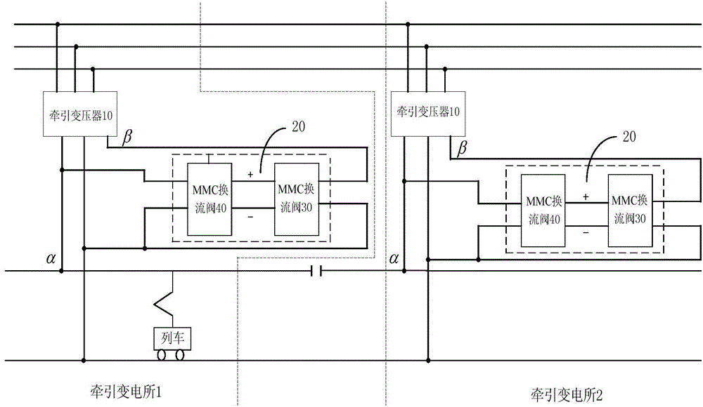
[0036] Such as figure 2 Shown is the composition structure and connection diagram of the in-phase power supply device and the traction power supply system provided by the present invention. The power system provides a 110kV / 220kV voltage power supply, which is converted into a 27.5kV / 55kV power supply by the traction transformer 10. After being transformed by the traction power supply system 20, the output Single-phase ...


PUM


Abstract

The invention discloses a co-phase power supply device and a traction power supply system. The co-phase power supply device comprises a first MMC (modular multilevel converter) valve and a second MMC valve. One end of the first MMC valve is coupled to a first power supply arm of a traction transformer, the other end of the first MMC valve is connected with a return wire, and the first MMC valve is used for converting AC (alternating current) voltage of the first power supply arm of the traction transformer into DC (direct current) voltage; one end of the second MMC valve is coupled to a second power supply arm of the traction transformer, the other end of the second MMC valve is connected with the return wire, and the second MMC valve is used for inverting DC voltage transmitted by the first MMC valve into AC voltage which is identical to the second power supply arm of the traction transformer in amplitude and phase. By means of inter-transmission of active energy of the two power supply arms on sides of the traction transformer, negative-phase sequence current can be eliminated, the capacity utilization rate of the traction transformer can be maximized and electric split-phase of a traction network can be eliminated; the MMC valves compensate idle power and harmonic waves of the two power supply arms, and the increase of risk of overhigh harmonic waves of devices such as capacitors, SVCs (static var compensator) and SVGs (static var generator) can be avoided, so that the co-phase power supply device can be applied to comprehensive treatment of power quality of traction transformers.

Description

technical field [0001] The invention relates to a power supply system, in particular to an in-phase power supply device and a traction power supply system. Background technique [0002] At present, most electrified railways in the world use AC power supply system, in which the power system provides 110kV / 220kV three-phase high-voltage power supply, which generally has a large capacity and can withstand large breaking current and harmonic current. The current AC power supply system stipulated by the IEC standard and the national standard is 27.5kV, 50Hz. Since the electric locomotive uses single-phase power supply, the higher-level 110kV / 220kV voltage provided by the power system must be converted into a single-phase 27.5kV voltage for the electric locomotive through the substation. [0003] Such as figure 1 As shown, in the traditional traction power supply system, the substation uses the traction transformer to convert the 110kV / 220kV high-voltage AC power supply into a 2...

Claims


Application Information

Patent Timeline
Patent Type & Authority Applications(China)
IPC IPC(8): B60M3/00H02M5/44H02M5/458
Inventor 张志学刘华东何多昌邓明罗文广
Owner CSR ZHUZHOU ELECTRIC LOCOMOTIVE RES INST
Why Eureka
Try Eureka