Lifting device special for rapidly lifting steel truss girder rod piece and using method

A technology for steel truss beams and rods, which is applied in the field of special hoisting tools for quickly hoisting steel truss beams and rods. Less, shorten the construction period, reduce the effect of construction cost

Active Publication Date: 2014-02-05
中铁二十一局集团路桥工程有限公司
View PDF7 Cites 2 Cited by
  • Summary
  • Abstract
  • Description
  • Claims
  • Application Information

AI Technical Summary

Problems solved by technology

This kind of hoisting method has many hidden dangers during construction. Since the steel truss girder members are wrapped in plastic bags, the steel truss girder members will inevitably be squeezed by the steel wire rope during hoisting, causing the plastic bags to rupture, which will still damage the steel truss girder members. The oil pollution caused by the truss members must be treated secondary to the steel truss members; secondly, it is greatly affected by human factors. It is easy to cause the steel wire rope to slide or even fall off, causing the center of gravity of the steel truss beam to shift, causing the steel truss beam to collide with the crane, or even the installed steel truss beam, causing construction accidents and requiring more auxiliary personnel , generally need 4~6 people to wrap steel truss beam members, high cost and low efficiency
At present, there is no better construction technology available in this field

Method used


Image

  • Lifting device special for rapidly lifting steel truss girder rod piece and using method
  • Lifting device special for rapidly lifting steel truss girder rod piece and using method
  • Lifting device special for rapidly lifting steel truss girder rod piece and using method

Examples


Embodiment Construction

[0018] The present invention will be described in further detail below in conjunction with accompanying drawing:

[0019] The technical scheme of the special spreader of the present invention is:

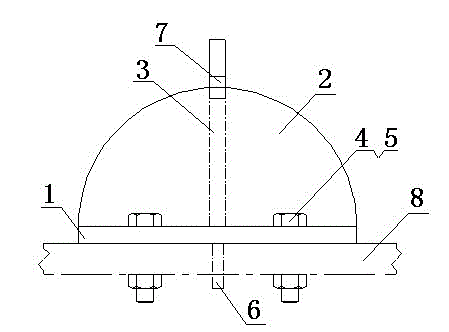
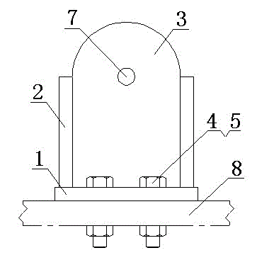
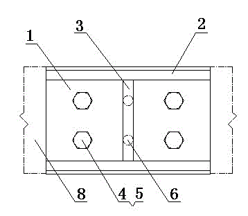
[0020] The side vertical plates (2) are respectively fixed on both sides of the flat bottom plate (1), the horizontal splint (3) is fixed in the middle of the side vertical plate (2), and two bolt holes are respectively opened on the flat bottom plates on both sides of the horizontal splint (3) ( 4), the fixing bolts (5) are installed in the bolt holes (4), the two positioning pins (6) are fixed under the flat bottom plate (1), and the distances between the two bolt holes (4) and the two positioning pins (6) are respectively It is exactly the same as the bolt hole spacing on the steel truss member (8) to be hoisted, and the upper part of the transverse splint (3) is provided with a hoisting hole (7);

[0021] The weight of the steel truss member (8) is less than 20 tons, the thickn...


PUM


Abstract

The invention discloses a lifting device special for rapidly lifting a steel truss girder rod piece and a using method. Side vertical plates are fixedly arranged on the two sides of a flat bottom plate respectively. A transverse clamping plate is fixedly arranged between the side vertical plates. Bolt holes are formed in the flat bottom plate. Positioning pins are fixedly arranged below the flat bottom plate. Intervals between the bolt holes and the positioning pins are completely consistent with those between bolt holes in the steel truss girder rod piece respectively. A lifting hole is formed in the upper part of the transverse clamping plate. When the lifting device is used, two special lifting devices are lifted to the two ends of the steel truss girder rod piece through a crane, fixing bolts are inserted into the bolt holes of the special lifting devices and the steel truss girder rod piece for fixation after the lifting devices are positioned respectively, the steel truss girder rod piece is lifted to a designed mounting position through the crane, and the fixing bolts are disassembled. According to the special lifting device, loosening and sliding in a lifting process can be avoided, secondary pollution to the rod piece can be avoided, the special lifting device is short in lifting time, high in reliability, easy to operate, high in construction speed, short in construction period and low in cost, and can be used for lifting steel truss girder rod pieces with different specifications, and a few matched operators are required.

Description

technical field [0001] The invention relates to a special spreader for steel components and a use method thereof, in particular to a special spreader for quickly lifting steel truss members and a use method thereof, belonging to the field of road and bridge construction. Background technique [0002] With the rapid development of road traffic, there are more and more phenomena of elevated railways and elevated highways crossing existing railway bridges or existing highway bridges. Due to the control and influence of the structure below the line and the overall height of the line, the steel truss structure is often used for the upper span bridge to meet the design requirements of the line. The steel truss girder is assembled from various types of steel rods. The weight of the rods ranges from a dozen tons to dozens of tons. How to quickly and smoothly hoist the steel truss rods to the designed installation position A key link in beam construction. [0003] The current const...

Claims


Application Information

Patent Timeline
Patent Type & Authority Applications(China)
IPC IPC(8): E01D21/00
Inventor 余长虹唐建运律百军周秀兰
Owner 中铁二十一局集团路桥工程有限公司
Why Eureka
Try Eureka