Suspension mold for enlarging and reinforcing concrete beam and construction method of suspension mold

A technology of concrete beams and construction methods, which is applied to the preparation of building components on site, the connectors of formwork/formwork/work frame, and building maintenance, etc., which can solve the problems of waste, complicated operation, and low construction efficiency

Inactive Publication Date: 2014-02-05
HANGZHOU GULI CONSTR ENG
View PDF8 Cites 5 Cited by
  • Summary
  • Abstract
  • Description
  • Claims
  • Application Information

AI Technical Summary

Problems solved by technology

With this method, the operation is complicated and a lot of scaffolding needs to be erected, the assembly and construction workload is large, the construction efficiency is low and the waste is serious
Mainly reflected in: 1. When setting up the roof support, since the usual steel pipe frames are mostly fixed in size, the height cannot be flexible and changeable, and it is difficult to meet the needs of different heights, and once the ground has a height difference or unevenness, it will affect the construction. 2. Because the length of the steel pipe does not match the required length, the phenomenon of random cutting, truncation, and lap joint is serious, resulting in waste of resources and management difficulties, and often cause construction quality problems due to improper lap joints; 3. Because the steel pipe is Round shape, the stress area of ​​the joint point with the wooden square is small, and the strength and deformation of the two materials are very different, so the wooden square is often deformed due to compression at the contact point, resulting in gaps during the construction process, resulting in grout leakage, etc. Happening

Method used


Image

  • Suspension mold for enlarging and reinforcing concrete beam and construction method of suspension mold

Examples


Embodiment Construction

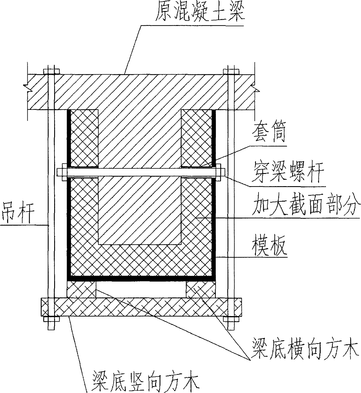
[0016] Such as figure 1 As shown, a kind of hanger formwork that a kind of concrete beam is used when increasing reinforcement, comprises concrete beam 1 and the floor slab 2 on concrete beam 1, is respectively provided with a suspender 3 on both sides of described concrete beam 1, these two One end of the boom 3 passes through the floor 2 and is fixed, and the other end is fixedly connected with a vertical square log 4, and the vertical square log 4 is provided with two horizontal square logs 5 on the left and right. A template 6 is provided, and the template 6 forms a closed grouting space 7 with the concrete beam 1, and the closed grouting space 7 is used for strengthening the concrete beam 1; a grouting hole 8 is also provided on the floor 2, and the grouting hole 8 Connected with the closed grouting space 7, concrete can be poured into the closed grouting space 7 from the grouting hole 8; the concrete beam 1 is also pierced with a beam-piercing screw 9, and the two ends o...


PUM


Abstract

The invention discloses a suspension mold for enlarging and reinforcing a concrete beam and a construction method of the suspension mold. The suspension mold comprises a concrete beam and a floor which is arranged on the concrete beam, wherein two sides of the concrete beam are respectively provided with a suspension rod, one end of each suspension rod penetrates through the floor to be fixed, the other end of each suspension rod is fixedly connected with a piece of a vertical square wood, each vertical square wood is provided with a left transverse square wood and a right transverse square wood, each transverse square wood is provided with a template, the template and the concrete beam form a closed grouting space, and the closed grouting space is used for enlarging and reinforcing the concrete beam; the floor is also provided with a grouting hole, and the grouting hole is communicated with the closed grouting space; a beam penetrating screw is also arranged on the concrete beam in a penetrating manner, and two ends of the beam penetrating screw also respectively penetrate through the template to be fixed. By adopting the structure, the stability of the template is reinforced, the pulp is unlikely to leak when the non-shrinkable grouting material is poured, and the deviation of the position of a construction axis caused by the existing of pipeline equipment below or on the side surface of a beam with the enlarged cross section can be avoided.

Description

technical field [0001] The invention discloses a hanging form used for strengthening concrete beams and a construction method of the hanging form, belonging to the technical field of building construction. Background technique [0002] Concrete beams generally appear in places such as high-rise buildings and bridges, and mainly play a supporting role in the entire building. In the process of construction, sometimes we need to strengthen the concrete beams. At this time, we generally use beam formwork scaffolding. This kind of scaffolding is mainly composed of wooden formwork, wooden squares and steel pipe supports to stabilize the formwork. With this method, the operation is complicated and a lot of scaffolding needs to be erected, the assembly and construction workload is large, the construction efficiency is low and the waste is serious. Mainly reflected in: 1. When setting up the roof support, since the usual steel pipe frames are mostly fixed in size, the height cannot ...

Claims


Application Information

Patent Timeline
Patent Type & Authority Applications(China)
IPC IPC(8): E04G17/18E04G23/02
Inventor 张宏金喜龙
Owner HANGZHOU GULI CONSTR ENG
Why Eureka
Try Eureka