Full Bore Layered Fracturing Sleeves for Oil and Gas Well Operations

A layered fracturing, full-bore technology, applied to wellbore/well valve devices, wellbore/well components, production fluids, etc. to avoid misoperation, improve reliability, and improve work efficiency

Active Publication Date: 2016-03-02
CHINA PETROLEUM & CHEM CORP +1
View PDF3 Cites 5 Cited by
  • Summary
  • Abstract
  • Description
  • Claims
  • Application Information

AI Technical Summary

Problems solved by technology

Using this type of sliding sleeve can achieve more limited stages, but because the hydraulic control pipeline needs to be lowered out of the casing to contact the open hole, the control pipeline may be damaged, and there is a risk that the sliding sleeve cannot be opened and the fracturing interval will be lost

Method used


Image

  • Full Bore Layered Fracturing Sleeves for Oil and Gas Well Operations
  • Full Bore Layered Fracturing Sleeves for Oil and Gas Well Operations
  • Full Bore Layered Fracturing Sleeves for Oil and Gas Well Operations

Examples


Embodiment 1

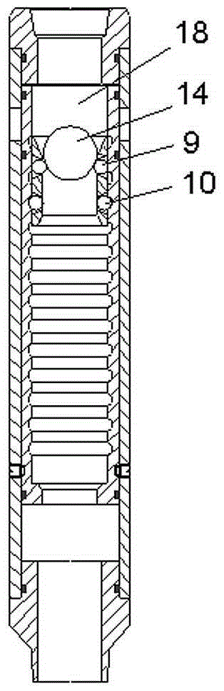
[0038] figure 1 What is shown is a structural form of the full-diameter layered fracturing sliding sleeve used in oil and gas well operations according to the present invention. In the outer cylinder 2 which is respectively connected with the upper joint 1 and the lower joint 7 at the two ends in the axial direction, a working cylinder with an integral structural form inner cylinder 5 structure which can be used for axial sliding is matched. There are shear pins 6 positioned with each other and a limit structure for limiting the sliding distance of the inner cylinder, and the upper part of the outer cylinder 2 is provided with a through guide hole 4 . in:

[0039] a. The inner peripheral surface of the inner cylinder 5 is provided with equally spaced groove structures 11 along the axial direction, and the groove structures 11 are continuous (or discontinuous) grooves arranged along the radial circumference. Cooperating with the groove structures 11, there is a step-type movi...

Embodiment 2

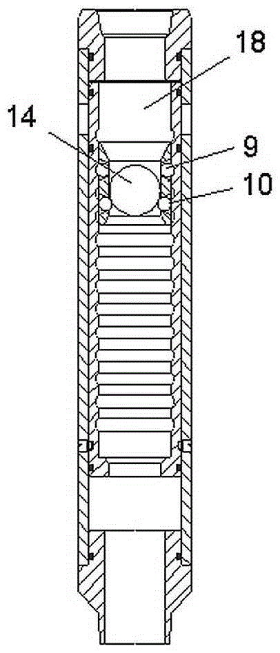
[0051] Figure 8~Figure 10 It is the structure of the overall structural form inner tube 5 structural form working cylinder of another structural form. The difference between it and Embodiment 1 is that the two groups of path switch structures 9, 10 at the axial interval on the step-type moving structure 8 are respectively the front and rear two groups connected to the step-type moving structure 8 through the elastic structure 15. Group claw structure 16,17.

[0052] After throwing the starting ball 14 from the uppermost sliding sleeve, the front claw structure 16 of the step-type moving structure 8 in the uppermost sliding sleeve inner cylinder 5 is located outside the groove structure 11 on the inner peripheral surface of the inner cylinder 5. The rear claw structure 17 is located in the groove structure 11 on the inner peripheral surface of the inner cylinder 5 . In this way, the starting ball 14 drops into and is blocked by the front group claw structure 16 outside the g...

Embodiment 3

[0057] This example is the structure of a kind of integral structural form inner cylinder 5 structural form working cylinders of combining above-mentioned embodiment 1 and above-mentioned embodiment 2 simultaneously.

[0058] Such as Figure 11 As shown, among the two groups of path switch structures 9 and 10 axially spaced on the step-type moving structure 8, the front group is a rolling structure 23, and the rear group is connected to the step-type moving structure 8 via an elastic structure 15. The elastic claw structure 17.

[0059] After throwing the starting ball 14 from the uppermost sliding sleeve, the rolling structure 23 of the step-type moving structure 8 in the inner cylinder 5 of the uppermost sliding sleeve is located outside the groove structure 11 on the inner peripheral surface of the inner cylinder 5. The claw structure 17 is located in the groove structure 11 on the inner peripheral surface of the inner cylinder 5 . In this way, the starting ball 14 is dro...


PUM


Abstract

The full -diameter layered fracture sliding cover for oil and gas well operation is set up in the form of cooperation with the outer cylinder. There are working tube including the inner tube that can move in the inner direction of the outer cylinder.There is a limited structure that is positioned and limited to the sliding distance of the inner tube. At least one axial end of the outer cylinder has a connector, and a diversion that can be connected with the inner cavity of the workpress of the workpress is set up.In the hole, there is a groove structure with intervals and grooves that can be turned over and can be used to the diameter of the starting ball with the diameter of the diameter.Control the diameter switching structure of the startup ball; the spacing of each adjacent groove on the inner wall of the working tube is non -integer that the distance between the diameter switch structure.The sliding cover of the present invention can achieve unlimited slide jackets. You only need to enter the same size to start the sliding cover step by step, which significantly improves the reliability of construction.The salvage of the tool greatly simplifies the construction process and improves operational efficiency.

Description

technical field [0001] The invention relates to a construction device for realizing annulus communication of an oil casing on a fracturing pipe string in oil and gas well completion operations, in particular to a full-diameter layered fracturing sliding sleeve for oil and gas well operations. Background technique [0002] In the process of oil and gas well completion and gas testing, the oil casing annulus is connected through the opening action of the sliding sleeve to realize circulation, fluid replacement, sand fracturing and other operations. In the structure of a traditional oil and gas well body, the fracturing string is a tubing, and multiple downhole tools such as packers, sandblasting sleeves, and sandblasting devices are connected to the fracturing string. The positions of sand blasters and sliding sleeves are fracturing layers, and the number of sand blasters and sliding sleeves represents the number of stages or stages of fracturing construction. Before the frac...

Claims


Application Information

Patent Timeline
Patent Type & Authority Patents(China)
IPC IPC(8): E21B34/14E21B43/26
Inventor 甘振维戚斌任山侯治民刘涛王磊王强胡顺渠
Owner CHINA PETROLEUM & CHEM CORP
Why Eureka
Try Eureka