Novel oil tank structure of compressed natural gas (CNG) hydraulic gas-filling substation prying body

A gas filling sub-station, a new type of technology, applied in the direction of fuel supply tank devices, mechanical equipment, etc., can solve the problems of increased fuel tank pressure, weak welding joint structure, and large consumption, so as to avoid pressure shock and make the overall structure easy to stabilize , the effect of reducing air loss

Inactive Publication Date: 2014-02-05
GTE GLOBAL TIANJIN
View PDF5 Cites 2 Cited by
  • Summary
  • Abstract
  • Description
  • Claims
  • Application Information

AI Technical Summary

Problems solved by technology

[0003] However, the disadvantages of this structure are also obvious
One is that after the compressed natural gas returns to the fuel tank, the pressure of the fuel tank increases instantaneously. Repeated long-term pressure impacts are a test for the sealing and structural strength of the fuel tank, which is likely to cause cracking of welding joints or structural weaknesses; the other is that the fuel tank needs to be filled with natural gas. After the overall pressure rises, the pressure detection switch will act, resulting in natural gas consumption. Each detection needs to consume 1-2m of natural gas 3 , although the amount is small, it is a lot of consumption in the long-term calculation

Method used


Image

  • Novel oil tank structure of compressed natural gas (CNG) hydraulic gas-filling substation prying body
  • Novel oil tank structure of compressed natural gas (CNG) hydraulic gas-filling substation prying body
  • Novel oil tank structure of compressed natural gas (CNG) hydraulic gas-filling substation prying body

Examples


Embodiment Construction

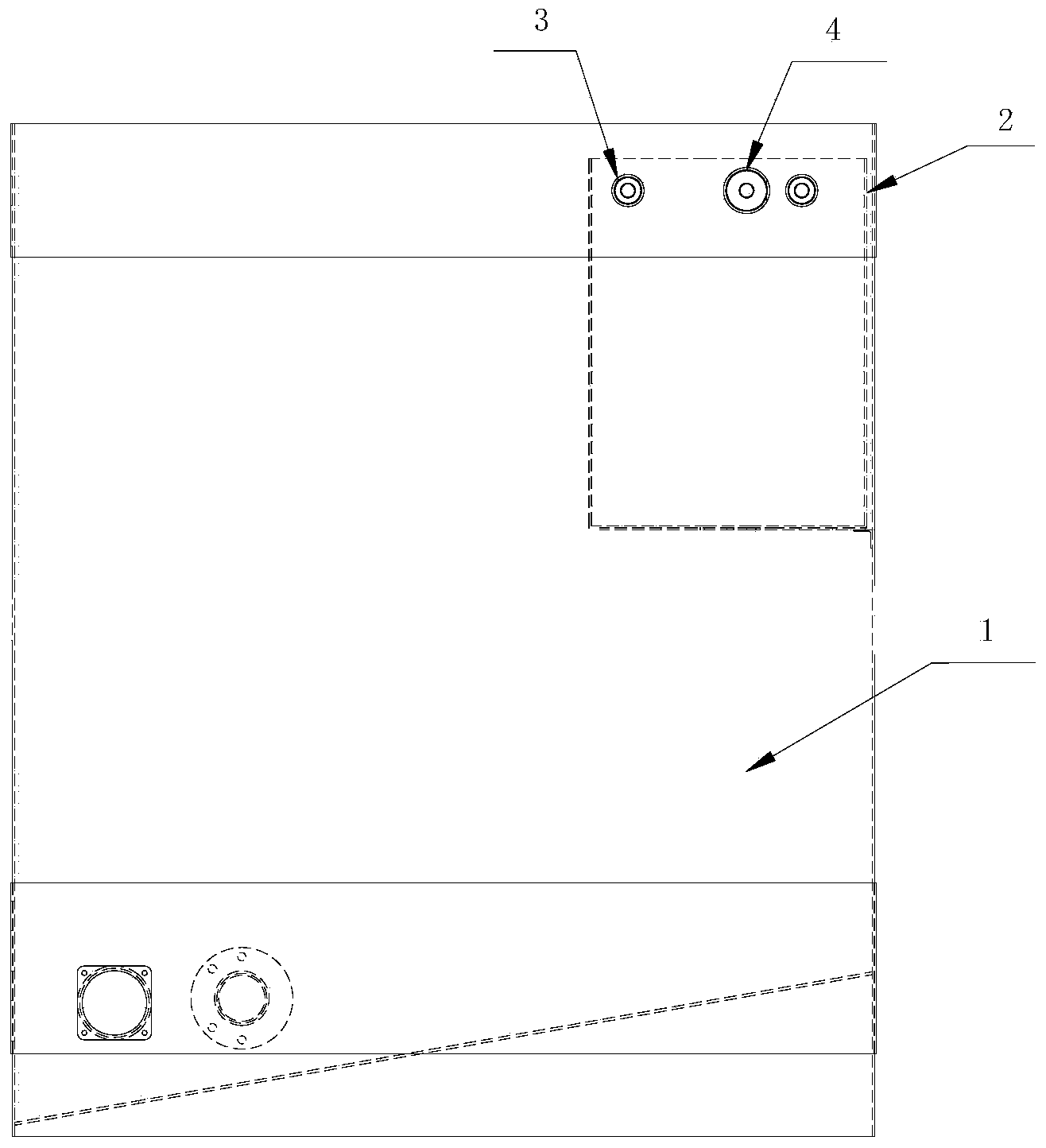
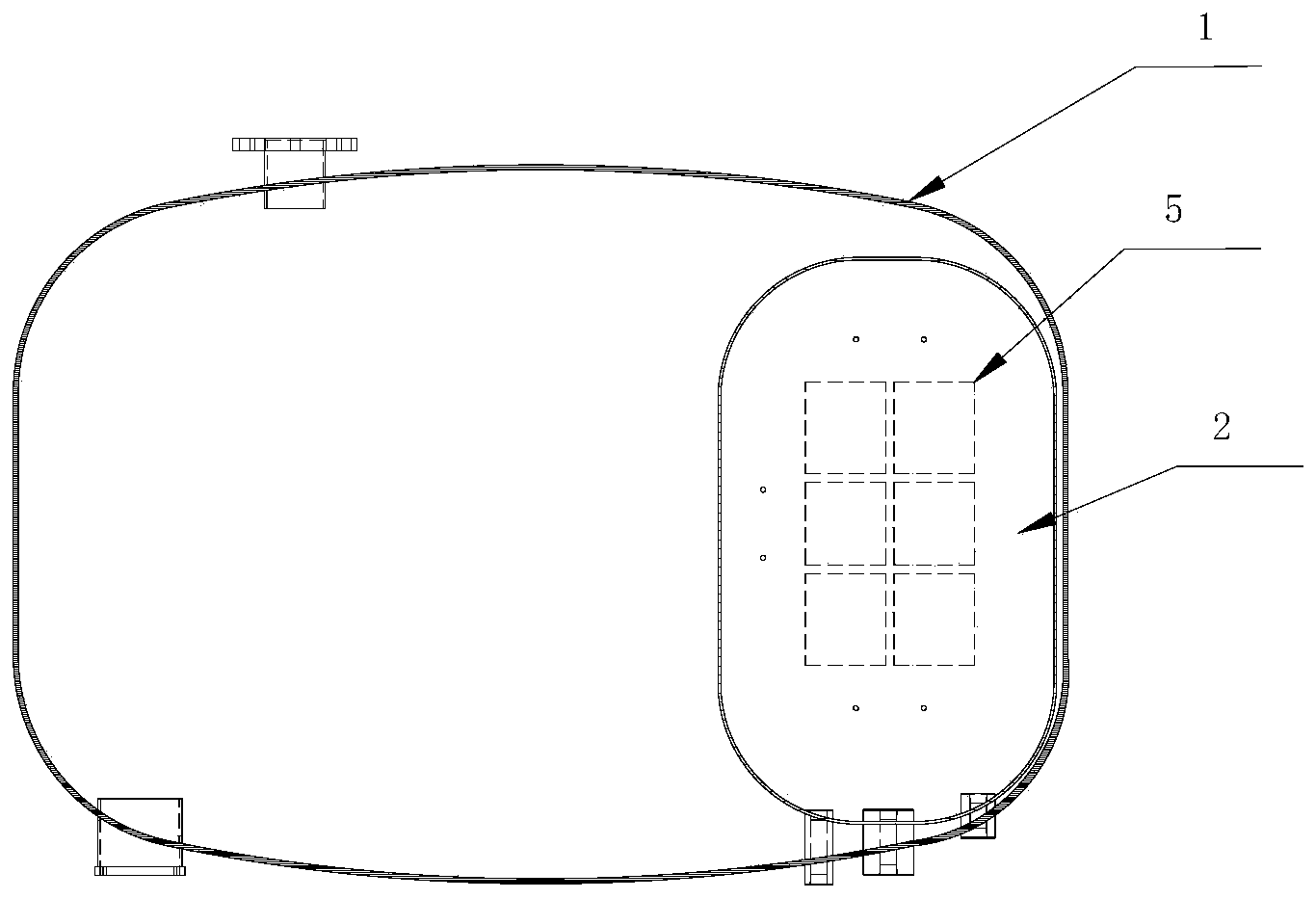
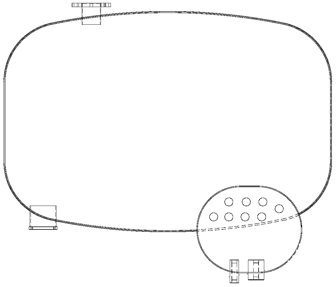
[0020] A new oil tank structure for a CNG hydraulic filling substation, comprising a main oil tank 1, an oil return detection oil tank 2 connected to the main oil tank 1, a pressure detection hole 3 and an oil return hole 4 connected to the oil return detection oil tank 2, and a return The oil detection oil tank 2 is provided with an oil return diffusion hole 5 communicating with the main oil tank 1 .

[0021] Such as figure 1 , 2 In the first embodiment shown, the oil return detection oil tank is set on the top of the main oil tank, the oil tank wall of the oil return control oil tank is thicker than that of the main oil tank, and the shape can be made into a pressure vessel structure with an overall ellipse or upper and lower heads, which is more durable pressure shock. The oil return diffusion hole is set at the bottom or lower part of the oil return detection oil tank to weaken the fluid impact of hydraulic oil and the pressure impact of natural gas during oil return. T...


PUM


Abstract

The invention provides a novel oil tank structure of a compressed natural gas (CNG) hydraulic gas-filling substation prying body. The novel oil tank structure comprises a main oil tank, a pressure detection hole and an oil return hole, wherein the pressure detection hole and the oil return hole are arranged in the main oil tank. An oil return detection oil tank is arranged in the main oil tank, the pressure detection hole and the oil return hole are communicated with the oil return detection oil tank, and the oil return detection oil tank is provided with an oil return diffusion hole communicated with the main oil tank. Thick plates and the firmer structure is adopted for the oil return detection oil tank, the main oil tank avoids direct pressure impact, the integrated structure is easy to stabilize, even thin plates can be adopted, and gas loss caused by detection of oil return pressure is greatly reduced.

Description

technical field [0001] The invention relates to the improvement of the oil tank structure of the skid of a CNG hydraulic gas filling sub-station. Background technique [0002] In the original structure, the hydraulic oil returns to the oil through the oil return hole. During this process, when the hydraulic oil returns to the net, CNG (compressed natural gas) returns to the fuel tank through the oil return hole, causing the internal pressure of the fuel tank to increase rapidly, and the pressure detection switch on the upper part of the fuel tank operates. The system closes the oil return solenoid valve, and the oil return process ends. This structure and method of detecting pressure are reliable and stable, and have been widely used in the industry for a long time. [0003] But the disadvantages of this structure are also obvious. One is that after the compressed natural gas returns to the fuel tank, the pressure of the fuel tank increases instantaneously. Repeated long-t...

Claims


Application Information

Patent Timeline
IPC IPC(8): F15B1/26
Inventor 姜增华
Owner GTE GLOBAL TIANJIN
Why Eureka
Try Eureka