Hydraulic system adopting independent compound control

A technology of hydraulic system and compound control, applied in the field of hydraulic system, can solve the problems of frequent opening and closing of safety valve, affecting the rapidity of acceleration process, prolonging adjustment time, etc., so as to improve system rigidity and dynamic performance, improve stability and efficiency, The effect of reducing throttling loss

Inactive Publication Date: 2020-06-12
FUJIAN UNIV OF TECH
View PDF8 Cites 2 Cited by
  • Summary
  • Abstract
  • Description
  • Claims
  • Application Information

AI Technical Summary

Problems solved by technology

During the acceleration process, the oil outlet side of the hydraulic pump still has a certain pressure, and it increases continuously with the increase of the hydraulic pump speed, which affects the rapidity of the acceleration process.
During the deceleration process, if the flow rate on the oil outlet side of the hydraulic pump differs greatly from its set value, a large pressure shock will be formed, which may even exceed the set pressure of the safety valve, causing the safety valve to frequently Opening and closing will have a great impact on system reliability and component life, and at the same time cause large fluctuations in the pressure on the oil outlet side, affecting the stability of the deceleration process
When the speed is controlled, when the speed of the hydraulic pump reaches the set value, the pressure on both sides cannot be balanced at the same time, and the speed will still fluctuate to a certain extent, causing the hydraulic pump to be unstable and prolonging the adjustment time.
[0007] Simply using the pump control system servo control response performance is slow, and the system rigidity is poor

Method used


Image

  • Hydraulic system adopting independent compound control
  • Hydraulic system adopting independent compound control
  • Hydraulic system adopting independent compound control

Examples


Embodiment Construction

[0028] specific implementation plan

[0029] In conjunction with accompanying drawing, introduce content of the present invention in detail:

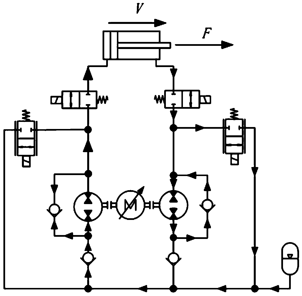
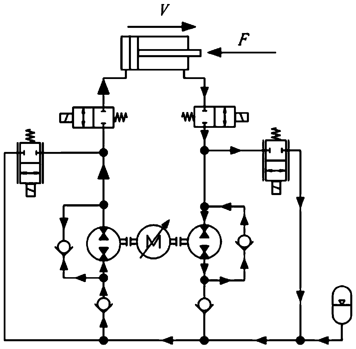
[0030] The hydraulic principle diagram of the technical scheme of the present invention is as follows figure 1 Shown:

[0031] 1. Hydraulic cylinder; 2, 3, two-position two-way solenoid valve; 4, 5, two-position two-way proportional throttle valve; 6, 7, two-way quantitative pump; 8, 9, 10, 11, one-way valve; 12 , variable speed motor; 13, accumulator.

[0032] As shown in the figure, hydraulic cylinder 1 has rod chamber end B oil port connected to E oil port of bidirectional quantitative pump 7, and a two-position two-way solenoid valve 3 is connected in series between BE oil ports, and two-position two-way solenoid valve 3 is used in the system The position of the hydraulic cylinder is fixed when it is not working or when it is necessary to keep the hydraulic cylinder in a static state; a check valve 9 is connected in parallel to t...


PUM


Abstract

The invention discloses a hydraulic system adopting independent compound control. The hydraulic system comprises a hydraulic cylinder, wherein a rod cavity end of the hydraulic cylinder is connected to a first two-way metering pump through a first solenoid valve; the first two-way metering pump is connected to a second two-way metering pump through a first one-way valve and a second one-way valve;the second two-way metering pump is connected to a piston cavity of the hydraulic cylinder through a second solenoid valve; the first two-way metering pump and the second two-way metering pump are driven by a variable-speed motor; an energy accumulator is further arranged between the first one-way valve and the second one-way valve; a third one-way valve is connected on the first two-way meteringpump in parallel; a fourth one-way valve is connected on the second two-way metering pump in parallel; a first proportional throttle valve is connected on the first two-way metering pump and the first one-way valve in parallel; a second proportional throttle valve is connected on the second two-way metering pump and the second one-way valve in parallel; and the solenoid valves, the proportional throttle valves and the variable-speed motor are controlled by a master controller.

Description

technical field [0001] The invention relates to the field of automatic control, in particular to an independent composite control hydraulic system. Background technique [0002] The development of the hydraulic system to the present, there are mainly three types of mature hydraulic systems classified according to the control form: ordinary control system, proportional control system, and servo control system. Proportional control system and servo control system are automatic hydraulic control systems with good stability, fast dynamic response and high accuracy. They are mainly used in various medium and high-end hydraulic machinery and devices. Naturally, they are expensive and difficult to maintain. Strict requirements on the use environment. [0003] The control loops commonly used in hydraulic engineering machinery include load sensing systems, positive flow control systems and negative flow control systems. [0004] In the traditional positive flow control system of co...

Claims


Application Information

Patent Timeline
Patent Type & Authority Applications(China)
IPC IPC(8): F15B1/02F15B11/08F15B13/04F15B20/00
CPCF15B1/02F15B11/08F15B13/04F15B20/00F15B2211/20576F15B2211/88
Inventor 张树忠唐一文练国富晏岱陈丙三
Owner FUJIAN UNIV OF TECH
Why Eureka
Try Eureka