Combination flow control valve of double pump

A control valve and double pump technology, applied in the field of hydraulic valves, can solve the problems of high installation space, complex structure and high cost, and achieve the effects of increasing stability and service life, increasing service life and improving protection.

Active Publication Date: 2020-02-07
江苏军源装备制造有限公司
View PDF7 Cites 1 Cited by
  • Summary
  • Abstract
  • Description
  • Claims
  • Application Information

AI Technical Summary

Problems solved by technology

In this way, for the unloading valve group, not only the structure is complex, the volume is large, and the installation space requirements are high during installation and use, but also the combination of multiple functional valves will make the cost higher

Method used


Image

  • Combination flow control valve of double pump
  • Combination flow control valve of double pump
  • Combination flow control valve of double pump

Examples


Embodiment Construction

[0031] The technical solutions of the present invention will be further described in detail below in conjunction with the accompanying drawings and embodiments.

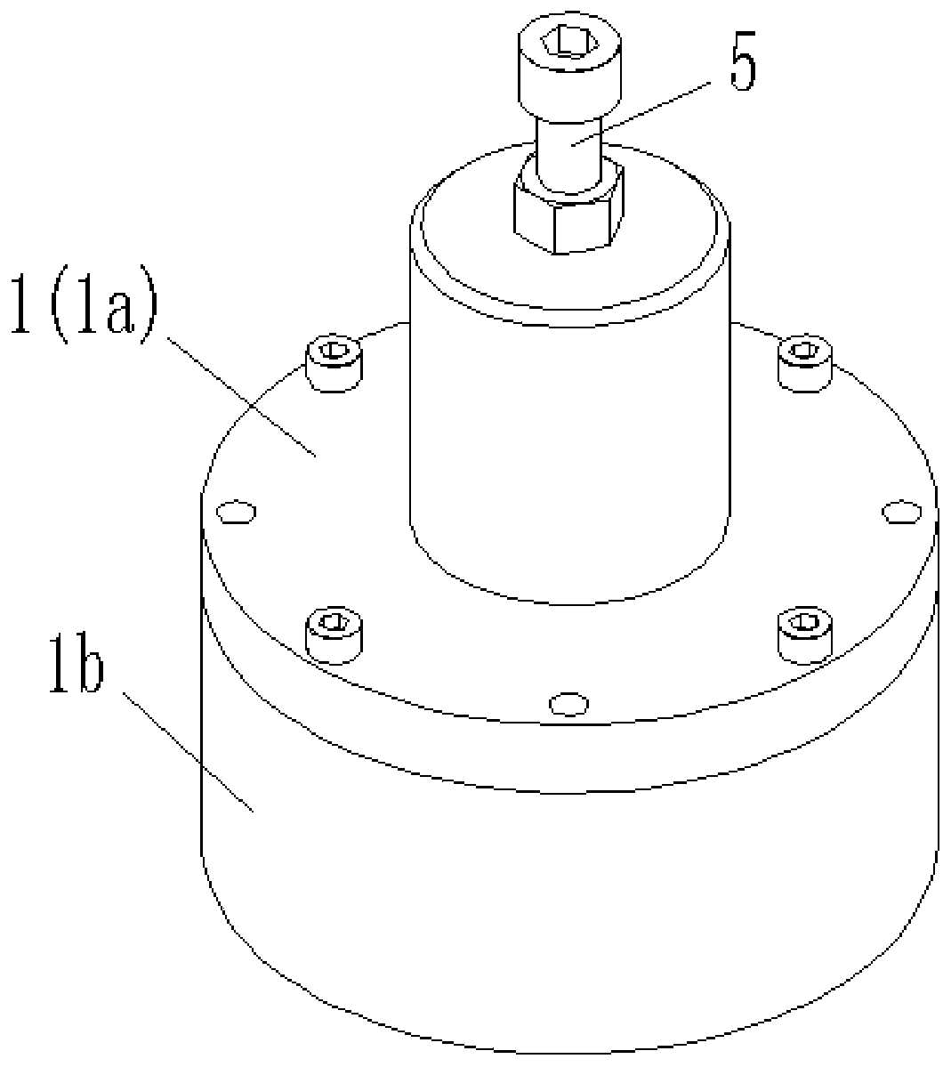
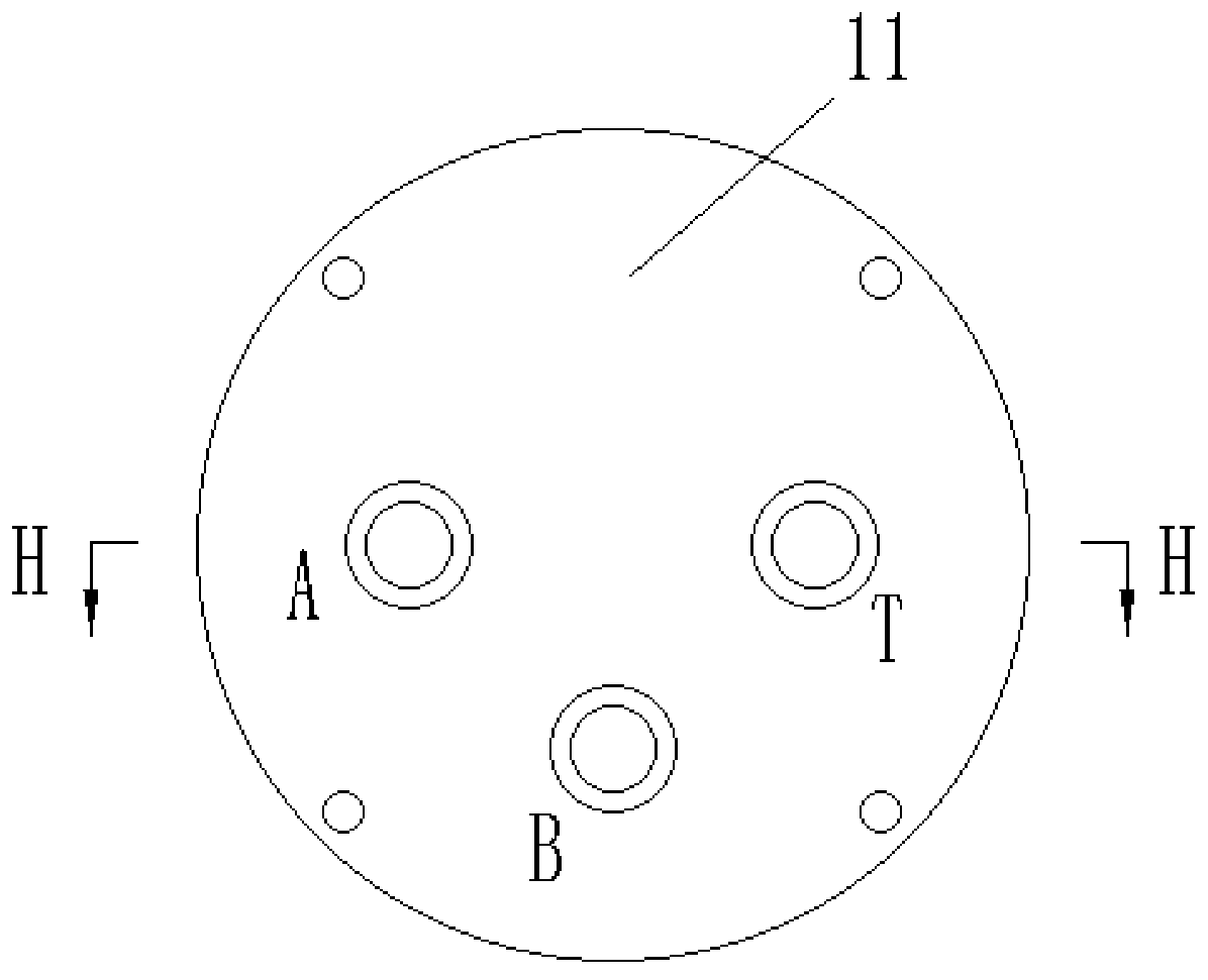
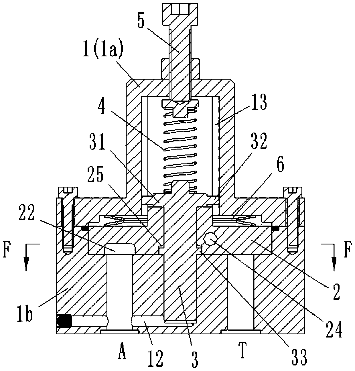
[0032] combine Figure 1 to Figure 3 As shown, the dual pump confluence control valve in this embodiment includes a valve body 1 , a valve core 2 and a control rod 3 . The mounting surface 11 of the valve body 1 is provided with A port, B port and T port which are not connected to each other, wherein, the A port is used to communicate with the outlet of the small flow pump, the B port is used to communicate with the outlet of the large flow pump, and the T port is used to communicate with the outlet of the large flow pump. The port is connected to the oil return tank. The control rod 3 is located inside the valve body 1 and can move back and forth axially relative to the valve body 1 . The valve core 2 has a disc structure and is sheathed on the control rod 3 inside the valve body 1 . Arc-shaped grooves 22 and aux...


PUM


Abstract

The invention belongs to the technical field of hydraulic valves, and discloses a combination flow control valve of a double pump. The combination flow control valve comprises a valve body, a valve element and a control rod. An opening A, an opening B and an opening T are arranged on the valve body. The control rod is located in the valve body and can do axial relative movement relative to the valve body. The valve element is of a disc type structure and is arranged on the control rod in the valve body in a sleeved manner, and the valve element is driven to rotate when the control rod axiallymoves. An arc groove and an auxiliary hole which are communicated through an inner duct are formed in the work end face of the valve element. In the process that the valve element rotates around the control rod, the opening B is communicated with one of the opening A and the opening T through the arc groove and the auxiliary hole, or the opening B, the opening A and the opening T are communicatedat the same time. When the opening B is communicated with the opening A through the arc groove, the opening T and the auxiliary hole keep closed. When the opening B is communicated with the opening Tthrough the arc groove, the opening A and the auxiliary hole keep closed or communicated. The combination flow control valve of the double pump is small in structural size and low in manufacturing cost, and multiple control functions can be achieved at the same time.

Description

technical field [0001] The invention belongs to the technical field of hydraulic valves, and in particular relates to a confluence control valve for double pumps. Background technique [0002] During the working process of the hydraulic machine, the slider on the machine generally needs to perform actions such as fast forward, working speed, and fast reverse, so as to realize specific action control. Among them, when performing fast forward and fast rewinding actions, the system flow is large and the pressure is low; when performing work speed actions, the system flow is small and the pressure is high. [0003] At present, when most hydraulic machines perform the above actions, they are generally completed by a hydraulic system composed of a double pump and an unloading valve group. When the slider is required to perform fast forward and rewind actions, the two pumps supply oil at the same time, and the system pressure is low; The small flow pump continues to supply oil, a...

Claims


Application Information

Patent Timeline
Patent Type & Authority Applications(China)
IPC IPC(8): F16K11/074F16K27/04F16K31/16F16K31/50F16K3/10
CPCF16K3/10F16K11/0743F16K27/045F16K31/16F16K31/502
Inventor 邵延荣宋海锋
Owner 江苏军源装备制造有限公司
Why Eureka
Try Eureka