Method for measuring diameter and coordinate position of spatial curved surface micro-hole in non-contact mode

A technology of non-contact measurement and coordinate position, which is applied in the field of non-contact measurement of the diameter and coordinate position of micro-holes on the space surface, measuring the diameter and coordinate position of micro-holes on the space surface of the blade body, and can solve the problem of inability to extract data and evaluation, and micro-hole images Blur and other problems, to achieve the effect of improving the level of processing technology

Active Publication Date: 2014-02-05
SHENYANG LIMING AERO-ENGINE GROUP CORPORATION
View PDF6 Cites 19 Cited by
  • Summary
  • Abstract
  • Description
  • Claims
  • Application Information

AI Technical Summary

Problems solved by technology

[0009] The purpose of the present invention is to provide a non-contact method for measuring the diameter and coordinate position of tiny holes on a curved surface in space. The precise positioning of the blade space is realized by using a two-axis precision turntable and a blade positioning device. Through a telecentric optical lens and a five-axis coordinate measuring machine Composite design and application, to solve the technical problem of fuzzy micro-hole images that cannot extract data and evaluate, realize digital precision measurement of the diameter and coordinate position of micro-holes on the measurement space surface, and provide a tool for effectively controlling the processing quality of aero-engine blade air film holes, etc. a viable method of measurement

Method used


Image

  • Method for measuring diameter and coordinate position of spatial curved surface micro-hole in non-contact mode
  • Method for measuring diameter and coordinate position of spatial curved surface micro-hole in non-contact mode
  • Method for measuring diameter and coordinate position of spatial curved surface micro-hole in non-contact mode

Examples


Embodiment

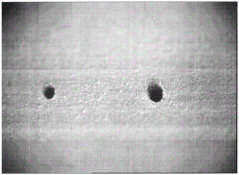
[0078] Air film holes in high-pressure turbine blades of aero-engines are tiny holes in the blade body, generally in the range of Φ0.3mm to Φ0.5mm, and are typical tiny holes on the space surface. Therefore, the present invention takes the detection of the diameter of the gas film hole of the high-pressure turbine blade and the coordinate position size as the embodiment of the present invention.

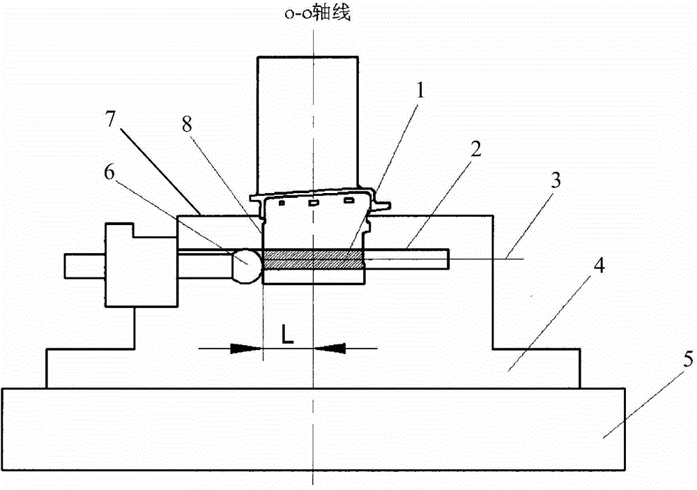
[0079] (1) Establishment of blade O-O axis

[0080] Adjust the positioning ball 6 according to the position of the blade O-O axis, so that the distance from the positioning ball 6 to the central rotation axis of the blade positioning device 4 is L, which is equal to the distance from the blade T reference plane 8 to the blade O-O axis, so as to ensure that the blade is in the tenon teeth 1 Accurate positioning in the length direction.

[0081] The clamping mechanism of the blade positioning device 4 adopts the principle of micro-deformation in design to avoid positioning errors caus...


PUM


Abstract

The invention belongs to the field of measurement of the diameter and the space coordinate geometric dimensioning of a spatial curved surface thin-wall micro-hole, and relates to a method for measuring the diameter and the coordinate position of the spatial curved surface micro-hole in a non-contact mode, in particular to the method for measuring the diameter and the coordinate position of the spatial curved surface micro-hole in a blade body of a blade by compositely designing and applying a telecentric optical lens and a five-axis coordinate measurement machine. A contact-type probe of the five-axis optical composite coordinate measurement machine is used for setting up a measuring basis of the diameter and the coordinate position of the spatial curved surface micro-hole of a workpiece, a two-dimensional rotating table is used for determining a spatial posture according to the direction of the axis of the spatial curved surface micro-hole, and the telecentric optical lens is used for extracting an image of the spatial curved surface micro-hole. The method can solve the difficult technical problem that data extraction and evaluation can not be conduced due to the fact that the image of the micro-hole is blurred, digitalized precise measurement of the diameter and the coordinate position of the spatial curved surface micro-hole is achieved, and the feasible measurement method is provided for effectively controlling machining quality of a gas film hole of the blade of an aviation engine and the like.

Description

technical field [0001] The invention belongs to the field of measuring the diameter of a thin-walled micro-hole on a curved space surface and the geometric dimensions of space coordinates, specifically a method for non-contact measurement of the diameter and coordinate position of a micro-hole on a curved space surface, in particular combining a telecentric optical lens with a five-axis coordinate measuring machine Composite design and application, and a method for measuring the diameter and coordinate position of tiny holes on the spatial curved surface of the blade body. Background technique [0002] In the prior art, the main methods and existing problems of measuring the diameter and coordinate position of the hole: [0003] (1) Three-coordinate measurement method [0004] Using a three-coordinate measuring machine and its equipped two-axis precision turntable (that is, a five-axis three-coordinate measuring machine), the measurement of the diameter and coordinate posit...

Claims


Application Information

Patent Timeline
Patent Type & Authority Applications(China)
IPC IPC(8): G01B11/08G01B11/00
Inventor 王呈穆轩王东刘鹏周永兆
Owner SHENYANG LIMING AERO-ENGINE GROUP CORPORATION
Why Eureka
Try Eureka