External field antenna pattern testing method

A technology of antenna pattern and test method, which is applied in directions such as antenna radiation pattern to reduce the number of movements, improve test efficiency, and improve measurement work efficiency.

Inactive Publication Date: 2014-02-05
UNIV OF ELECTRONICS SCI & TECH OF CHINA
View PDF6 Cites 37 Cited by
  • Summary
  • Abstract
  • Description
  • Claims
  • Application Information

AI Technical Summary

Problems solved by technology

[0004] The purpose of the present invention is to overcome the deficiencies of the prior art, and provide a method for testing the antenna pattern in the field, so as to realize the test of the antenna pattern in the situation that the antenna unit is not disas

Method used


Image

  • External field antenna pattern testing method
  • External field antenna pattern testing method
  • External field antenna pattern testing method

Examples


Embodiment Construction

[0028] The specific embodiments of the present invention are described below in conjunction with the accompanying drawings, so that those skilled in the art can better understand the present invention. It should be particularly noted that in the following description, when detailed descriptions of known functions and designs may dilute the main content of the present invention, these descriptions will be omitted here.

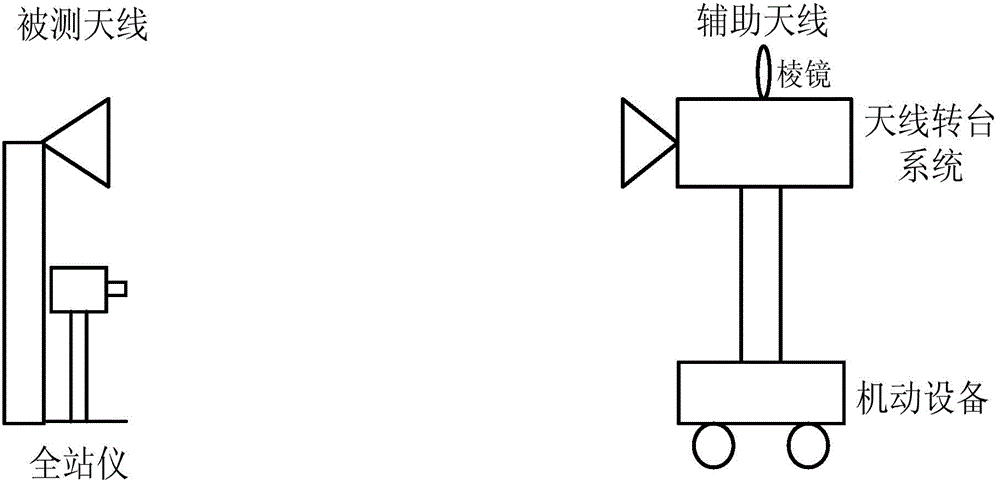
[0029] When testing the field antenna pattern, the equipment erection diagram is as follows figure 1 As shown, the specific process is as follows:

[0030] Install the auxiliary antenna on the antenna turntable system, and move it to a distance of R meters directly in front of the antenna under test that meets the requirements of the field distance. In this embodiment, the test distance R is based on the field test distance formula R≥KD 2 / λ calculation, where D is the diameter of the tested antenna and K is a constant, usually K≥2. In this embodiment, the frequenc...


PUM


Abstract

The invention discloses an external field antenna pattern testing method. A test station is looked for as an auxiliary antenna and an antenna rotation platform system are installed on a mobile maneuvering device and move around a measured antenna; a total station in an optical surveying and mapping instrument is innovatively adopted for locating the angle and the distance when the antenna moves and a test station with the corresponding deviation angle can be accurately located. By the adoption of the test station locating method where the maneuvering device, the total station in the optical surveying and mapping instrument and the antenna rotation platform system are combined, the measuring angle can be located accurately to local conditions under conditions of an external field. Meanwhile, after the measuring station is located, the total station is used for automatically tracking azimuth information and a horizontal scan frame on the antenna rotation platform system is used for moving the auxiliary antenna, so that the auxiliary antenna can be accurately located at all measuring stations within a certain measurement angle range at each measuring station, the moving frequency of the maneuvering device is lowered, errors brought by moving of the maneuvering device are reduced and the testing efficiency is improved.

Description

Technical field [0001] The invention belongs to the technical field of test and measurement, and more specifically, relates to a test method of antenna pattern under external field environmental conditions. Background technique [0002] As antennas are used more and more widely in radio systems such as radar and communications, the measurement of antennas has attracted more and more attention. There are many technical indicators for antenna measurement. The antenna pattern characterizes the antenna’s ability to radiate electromagnetic waves in space and reflects the antenna’s performance indicators and working status. Therefore, measuring and analyzing the antenna pattern can analyze the antenna’s radiation characteristics. Provide analysis data for the debugging, installation, maintenance, and overhaul of the antenna during use, and determine whether the performance index of the antenna meets the requirements and whether the antenna is faulty. [0003] At present, the test of ant...

Claims


Application Information

Patent Timeline
IPC IPC(8): G01R29/10
Inventor 李力张朋黄建国唐煌刘华杰吴万东
Owner UNIV OF ELECTRONICS SCI & TECH OF CHINA
Why Eureka
Try Eureka