
Electric stripping machine

A peeling machine and electric technology, applied in the direction of circuits, electrical components, circuit/collector components, etc., can solve the problems of large number of machines, waste of resources, high labor costs, etc., achieve fast response, good quiet performance, and reduce production cost effect

Active Publication Date: 2014-02-05
WELL SHIN ELECTRONICS KUNSHAN
View PDF5 Cites 11 Cited by
  • Summary
  • Abstract
  • Description
  • Claims
  • Application Information

AI Technical Summary

Problems solved by technology

The existing stripping machine uses a cylinder to drive the cutting blade to strip the wires. It can only peel one specification and one size of wire at a time. If different types (such as single-core, double-core, and three-core , multi-core) wires are stripped, you need to replace the blade or switch to another stripping machine for operation, the labor cost is high, and the number of machines required is large, resulting in a great waste of resources

Method used


Image

  • Electric stripping machine
  • Electric stripping machine
  • Electric stripping machine

Examples


Embodiment Construction

[0017] The present invention will be specifically introduced below in conjunction with the accompanying drawings and specific embodiments.

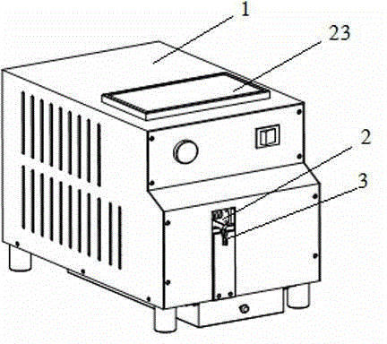
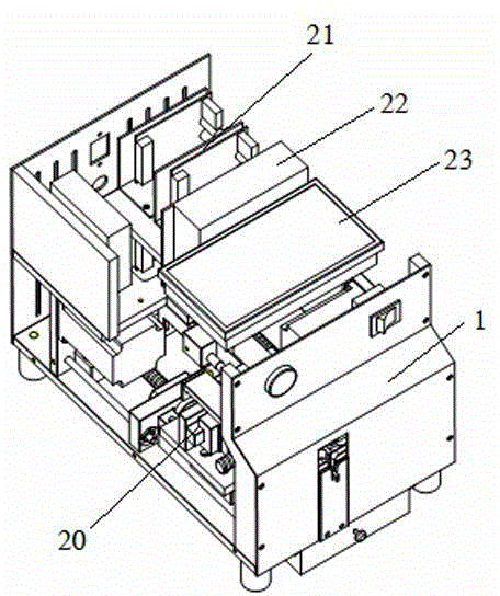
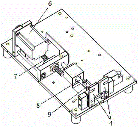
[0018] see Figure 1 to Figure 5 , a kind of electric stripping machine of the present invention, comprises housing 1, and housing 1 is provided with clamping mechanism, peeling mechanism, peeling mechanism and electric control mechanism inside, and each mechanism cooperates to peel off the insulation layer outside electric wire 5. Depend on figure 1 and figure 2 It can be seen that a power supply wire 5 is formed on the side of the housing 1 so that the wire 5 accommodating structure for clamping by the wire clamping mechanism is formed. As a preference, the wire accommodating structure is a through hole 2 formed on the housing 1, and the through hole can be It is square or circular, and has a groove 3 below the through hole 2 , the groove 3 is strip-shaped, and is located between a pair of clamps 4 . In this way, when the peeling ma...


PUM


Abstract

The invention discloses an electric stripping machine which comprises a shell. A wire clamping mechanism, a stripping mechanism, a peeling mechanism and an electric control mechanism are arranged inside the shell, and an electric wire containing structure where electric wires stretch to be clamped by the wire clamping mechanism is formed in the side face of the shell. The electric stripping machine has the advantages of being capable of rapidly and accurately striping an insulated layer of the electric wires, good in stripping quality, and free of damage to an inner core; in addition, stripping for the electric wires of different specifications and different sizes is achieved simply by setting different technologies on a touch screen, production efficiency is improved, human cost is saved, and machine requirements are reduced; production cost is further greatly reduced, and due to the fact that electric control is adopted, mute performance is good, and reaction speed is high.

Description

technical field [0001] The invention relates to an electric peeling machine, which belongs to the field of mechanical automation. Background technique [0002] The wire includes a core and an insulating layer. When wiring, the insulating layer at the end of the wire must first be peeled off to expose the core, which is convenient for the core to connect with other conductors to achieve conduction. The existing stripping machine uses a cylinder to drive the cutting blade to strip the wires. It can only peel one specification and one size of wire at a time. If different types (such as single-core, double-core, and three-core , multi-core) wires for stripping, you need to replace the blade or switch to another stripping machine for operation, the labor cost is high, and the number of machines required is large, resulting in a great waste of resources. Contents of the invention [0003] In order to solve the deficiencies of the prior art, the purpose of the present invention...

Claims


Application Information

Patent Timeline
Patent Type & Authority Applications(China)
IPC IPC(8): H02G1/12H01R43/28
Inventor 陈静江
Owner WELL SHIN ELECTRONICS KUNSHAN
Learn More