a power device

A technology of power equipment and power packs, applied in the direction of generators/motors, electrical components, etc., can solve the problems of large energy consumption, large amount of harmful gas emissions, low power efficiency, etc., and achieve the effect of high efficiency and wide application field

Inactive Publication Date: 2015-10-07
冯福荣
View PDF6 Cites 0 Cited by
  • Summary
  • Abstract
  • Description
  • Claims
  • Application Information

AI Technical Summary

Problems solved by technology

[0006] Whether it is an external combustion engine, an internal combustion engine or an electric motor, the energy consumption is relatively large, the power efficiency is not high, and the emission of harmful gases is relatively large, which is not energy-saving and environmentally friendly.

Method used


Image

  • a power device
  • a power device
  • a power device

Examples


Embodiment 1

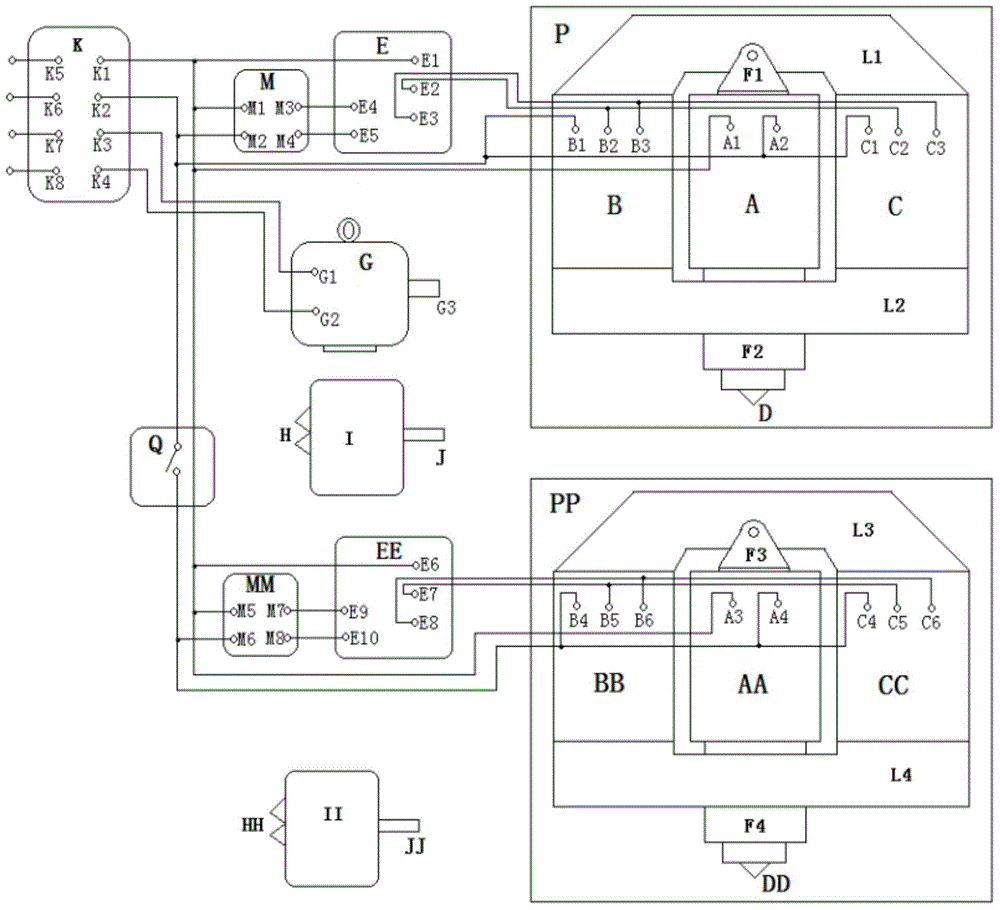
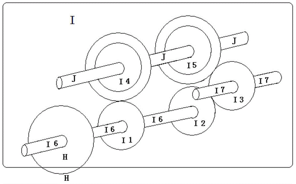
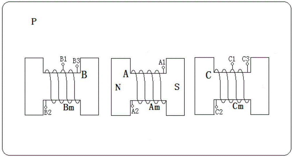
[0056] See Figure 1-Figure 4 , figure 1 It is a schematic structural diagram of the power equipment in Embodiment 1 of the present invention; figure 2 It is a schematic structural view of the combined gearbox 1 in the power equipment of Embodiment 1 of the present invention; image 3 It is a schematic structural diagram of the power group P in the power equipment of Embodiment 1 of the present invention; Figure 4 It is a schematic structural diagram of the square-wave current shunt generator E in the power equipment of Embodiment 1 of the present invention.

[0057] The power equipment provided by the embodiment of the present invention uses a forced scheme to alternately change the orientation of the magnetic field poles to generate a periodic power source. A power group P is composed of the three excitations of the mover excitation A and the stator excitation B and C. At the same time, it can also be set up to combine two or more power groups P in parallel and the powe...

Embodiment 2

[0065] See Figure 5 , which is a schematic structural diagram of the power group P1 in the power equipment according to Embodiment 1 of the present invention.

[0066] The power equipment provided in this embodiment uses a forced scheme to alternately change the orientation of the magnetic field poles to generate a periodic power source. The rest of the structure of this embodiment is the same as that of Embodiment 1, and the only difference is: the stator excitation B is wound by the stator excitation coil Bm, the stator excitation coil Bm is a single winding, the stator excitation C is wound by the stator excitation coil Cm, and the stator excitation coil Cm is A single winding, the mover excitation A is a permanent magnet or a de-excitation winding, which is made of silicon steel or silicon steel or other magnetically permeable materials.


PUM


Abstract

The invention discloses power equipment. Compulsory schemes are used for alternatively changing directions of magnetic poles of magnetic fields to generate periodical power sources. The power equipment mainly comprises a rectangular wave current branch generator, a speed regulator, a power set, a direct-current power supply and a composite gear box. Compared with the prior art, the power equipment has the advantages of saving energy, being free of emission, high in efficiency and wide in application field and the like because the directions of the magnetic poles of the magnetic fields are alternatively changed by the compulsory schemes to generate the periodical power sources.

Description

technical field [0001] The invention relates to the field of equipment for providing power, specifically a kind of power equipment. Background technique [0002] An engine is a machine that can convert other forms of energy into mechanical energy, including internal combustion engines (gasoline engines, etc.), external combustion engines (Stirling engines, steam engines, etc.), electric motors, etc. For example, internal combustion engines usually convert chemical energy into mechanical energy. The engine is not only applicable to the power generation device, but also refers to the whole machine including the power device (such as: gasoline engine, aero engine). The engine is a complete set of power output equipment, including transmission gears, engines and transmission shafts, etc. It can be seen that the engine is only a part of the entire engine, but it is the core part of the entire engine. People continue to develop various types of engines, which can be mainly divid...

Claims


Application Information

Patent Timeline
Patent Type & Authority Patents(China)
IPC IPC(8): H02N11/00
Inventor 冯福荣
Owner 冯福荣
Why Eureka
Try Eureka