Method and device for correcting focus of CT (computed tomography) machine

A focus and focus offset technology, applied in the field of optical scanning, can solve the problems of high cost, difficult correction, slow adjustment speed, etc., to achieve the effect of avoiding cost, fast correction speed and satisfying real-time performance

Active Publication Date: 2014-02-12
NEUSOFT MEDICAL SYST CO LTD
View PDF6 Cites 13 Cited by
  • Summary
  • Abstract
  • Description
  • Claims
  • Application Information

AI Technical Summary

Problems solved by technology

However, the mechanical method in the prior art must be naturally limited by the mechanical movement, it is difficult to realize real-time and fast correction, and the adjustment speed is relatively slow; and the hardware transformation brought by the mechanical method also has a relatively high cost.

Method used


Image

  • Method and device for correcting focus of CT (computed tomography) machine
  • Method and device for correcting focus of CT (computed tomography) machine
  • Method and device for correcting focus of CT (computed tomography) machine

Examples


Embodiment Construction

[0047] In order to make the purpose, technical solutions and advantages of the embodiments of the present invention clearer, the technical solutions in the embodiments of the present invention will be clearly and completely described below in conjunction with the drawings in the embodiments of the present invention. Obviously, the described embodiments It is a part of embodiments of the present invention, but not all embodiments. Based on the embodiments of the present invention, all other embodiments obtained by persons of ordinary skill in the art without making creative efforts belong to the protection scope of the present invention.

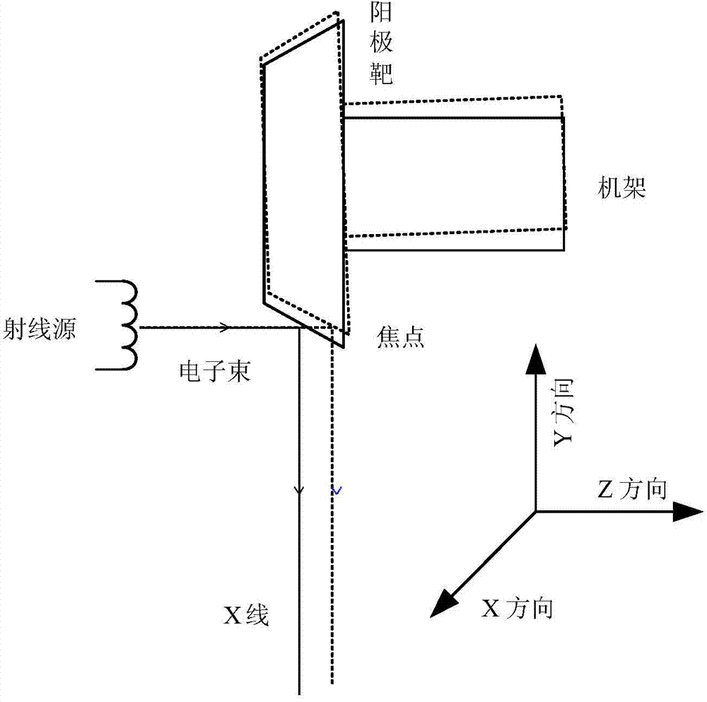
[0048] In the present invention, the correction of the focus position of the CT machine is no longer carried out by mechanical means; but by calculating the focus offset under the mechanical error, and correcting the angle of the electron beam emitted by the ray source according to the offset, thereby ensuring The electron beam can be refract...


PUM


Abstract

An embodiment of the invention provides a method and a device for correcting a focus of a CT (computed tomography) machine. The method comprises the steps as follows: the total focus offset is calculated according to scanning working condition data; and in an operation process of the CT machine, deflection correction is performed on an electron beam emitted by a radiation source by the aid of the total focus offset. The device comprises an offset calculation module and an offset correction module, wherein the offset calculation module is used for calculating the total focus offset according to the scanning working condition data; and the offset correction module is used for performing deflection correction on the electron beam emitted by the radiation source by the aid of the total focus offset.

Description

technical field [0001] The invention relates to the field of optical scanning technology, in particular to a method and device for correcting the focus of a CT machine. Background technique [0002] CT machine (Computed Tomography, the full name is computerized tomography system) is a very common imaging diagnostic instrument in medicine. Simply put, tomography using X-rays [0003] The structure and principle of the CT machine are as follows: a ball tube is used as the ray source, and the cathode of the ball tube generates electron beams under the action of a high-voltage filament. Imaging diagnosis. Such as figure 1 shown. [0004] Because medical CT machines have very high requirements for accuracy, the control of radiation by CT machines is extremely strict. For the control of the direction and angle of the ray, a very critical link is the focus position of the ray. The so-called focus is the point where the electron beam refracts on the anode target. It can be sai...

Claims


Application Information

Patent Timeline
Patent Type & Authority Applications(China)
IPC IPC(8): A61B6/03
CPCA61B6/032A61B6/4021A61B6/405A61B6/54A61B6/586
Inventor 李双学相欣蒋哲文
Owner NEUSOFT MEDICAL SYST CO LTD
Why Eureka
Try Eureka