
A shot blasting machine cleaning device and method

A technology of cleaning device and shot blasting machine, which is applied in the direction of abrasive feeding device, used abrasive processing device, abrasive jetting machine tool, etc. It can solve the problems of low precision, low degree of automation, and no theoretical data, etc.

Active Publication Date: 2016-10-05
JIANGSU LONGCHENG CASTING MACHINERY TECH
View PDF8 Cites 0 Cited by
  • Summary
  • Abstract
  • Description
  • Claims
  • Application Information

AI Technical Summary

Problems solved by technology

[0005] (1) The steel plate workpieces thrown by the steel plate shot blasting machine currently used in the shot blasting machine industry, because the requirements of the steel plate shot blasting machine are much higher than those of ordinary shot blasting machines, it can be clearly seen on the discharge roller table There are scattered steel sand and dust, which cannot meet the requirements of the next painting process;
[0006] (2) The cleaning device used on the steel plate shot blasting machine has a low degree of automation, and the operator has to manually lift up and down according to the thickness of the workpiece; the precision is low, and it is easy to cause the steel plate workpiece to be stuck;
[0007] (3) The arrangement positions of the scraper device, rolling brush device and blasting device in the cleaning device of most steel plate shot blasting machines are made according to the experience of the production workers, there is no theoretical data, and there is no design of the width of the shot blasting steel plate according to the needs The distance between the above three cleaning devices, so the cleaning effect is often not up to the due requirements

Method used

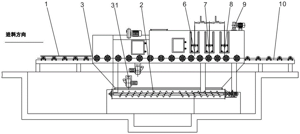
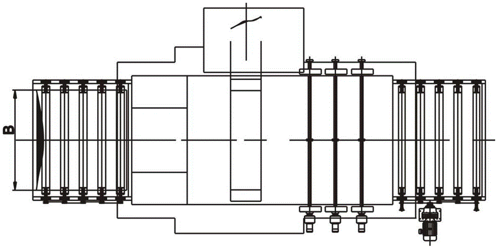
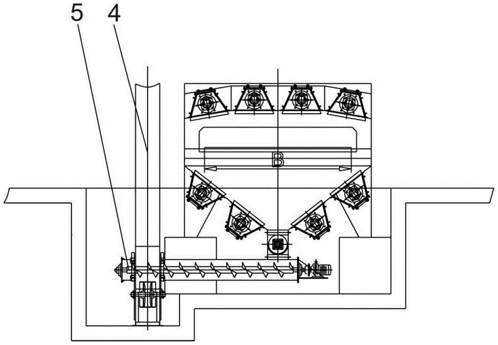

Image

  • A shot blasting machine cleaning device and method
  • A shot blasting machine cleaning device and method
  • A shot blasting machine cleaning device and method

Examples


Embodiment Construction

[0034] In order to make the above objects, features and advantages of the present invention more comprehensible, the specific implementation of the present invention will be described in detail below in conjunction with specific examples.

[0035] In the following description, a lot of specific details are set forth in order to fully understand the present invention, but the present invention can also be implemented in other ways different from those described here, and those skilled in the art can do it without departing from the meaning of the present invention. By analogy, the present invention is therefore not limited to the specific examples disclosed below.

[0036] Second, "one embodiment" or "an embodiment" referred to herein refers to a specific feature, structure or characteristic that may be included in at least one implementation of the present invention. "In one embodiment" appearing in different places in this specification does not all refer to the same embodime...


PUM


Abstract

The invention discloses a shot blasting machine cleaning device and method, wherein the shot blasting machine cleaning device includes a shot blasting cleaning room, a plurality of shot blasting devices are installed on the outer wall of the shot blasting machine; The shot outlet of the chamber is connected; the bucket elevator has a material inlet and an outlet; the horizontal conveying auger, one end of which is connected with the outlet of the bucket elevator; and a cleaning device, which includes a scraper Plate device, paint rolling device and blasting device, and the distance between scraper device, paint rolling device and blasting device shall be 50mm≤1200mm. This invention aims at the problems existing in the steel plate shot blasting equipment in the existing industry, and adopts a new type of three-way cleaning device to ensure that the cleaned steel plate is free of scattered steel shots and dust.

Description

technical field [0001] The invention relates to a shot blasting equipment and a method for cleaning a thin plate by using the equipment, in particular to a shot blasting machine cleaning device and method. Background technique [0002] Shot blasting machine is a shot blasting equipment that uses high-speed projectiles thrown by a shot blaster to clean or strengthen the surface of castings. The shot blasting machine can shake out sand, remove core and clean the casting at the same time. [0003] Shot blasting equipment is firstly used to remove sand and scale on the surface of cast steel and iron castings in the foundry industry. Almost all steel castings, gray castings, malleable steel parts, ductile iron parts, etc. must be shot blasted. This is not only to remove scale and sticky sand on the surface of the casting, but also an indispensable preparation process before the quality inspection of the casting. For example, the casing of a large gas turbine must be subjected t...

Claims


Application Information

Patent Timeline
Patent Type & Authority Patents(China)
IPC IPC(8): B24C3/02B24C5/00B24C7/00B24C9/00
Inventor 江兴平胡兆群徐增荣
Owner JIANGSU LONGCHENG CASTING MACHINERY TECH
Learn More