Flaring machine of plastic-steel-plastic composite pressure pipe

A technology of steel-plastic composite and pressure pipes, which is applied in the field of auxiliary installation equipment for steel-plastic composite pressure pipes, can solve the problems of high labor intensity for operators, small diameter of applicable pipes, and low degree of automation, so as to improve the degree of installation automation and reduce work Strength, efficiency-enhancing effects

Inactive Publication Date: 2014-02-12
NINGBO KANGRUN MACHINERY TECH
View PDF3 Cites 3 Cited by
  • Summary
  • Abstract
  • Description
  • Claims
  • Application Information

AI Technical Summary

Problems solved by technology

[0003] At present, the connection tools used for the connection of steel-plastic composite pressure pipe flared pipe fittings include manual mechanical flaring tools and jack rubber block type flaring tools, but the above-mentioned flaring tools have low automation and high labor intensity for operators. Defects such as the relatively small caliber of the pipe cannot well meet the application of flared fittings for steel-plastic pipes in the connection of steel-plastic composite pressure pipes, and at the same time restrict the product promotion of steel-plastic composite pressure pipes

Method used


Image

  • Flaring machine of plastic-steel-plastic composite pressure pipe
  • Flaring machine of plastic-steel-plastic composite pressure pipe
  • Flaring machine of plastic-steel-plastic composite pressure pipe

Examples


Embodiment Construction

[0022] The preferred embodiments of the present invention will be described below in conjunction with the accompanying drawings. It should be understood that the preferred embodiments described here are only used to illustrate and explain the present invention, and are not intended to limit the present invention.

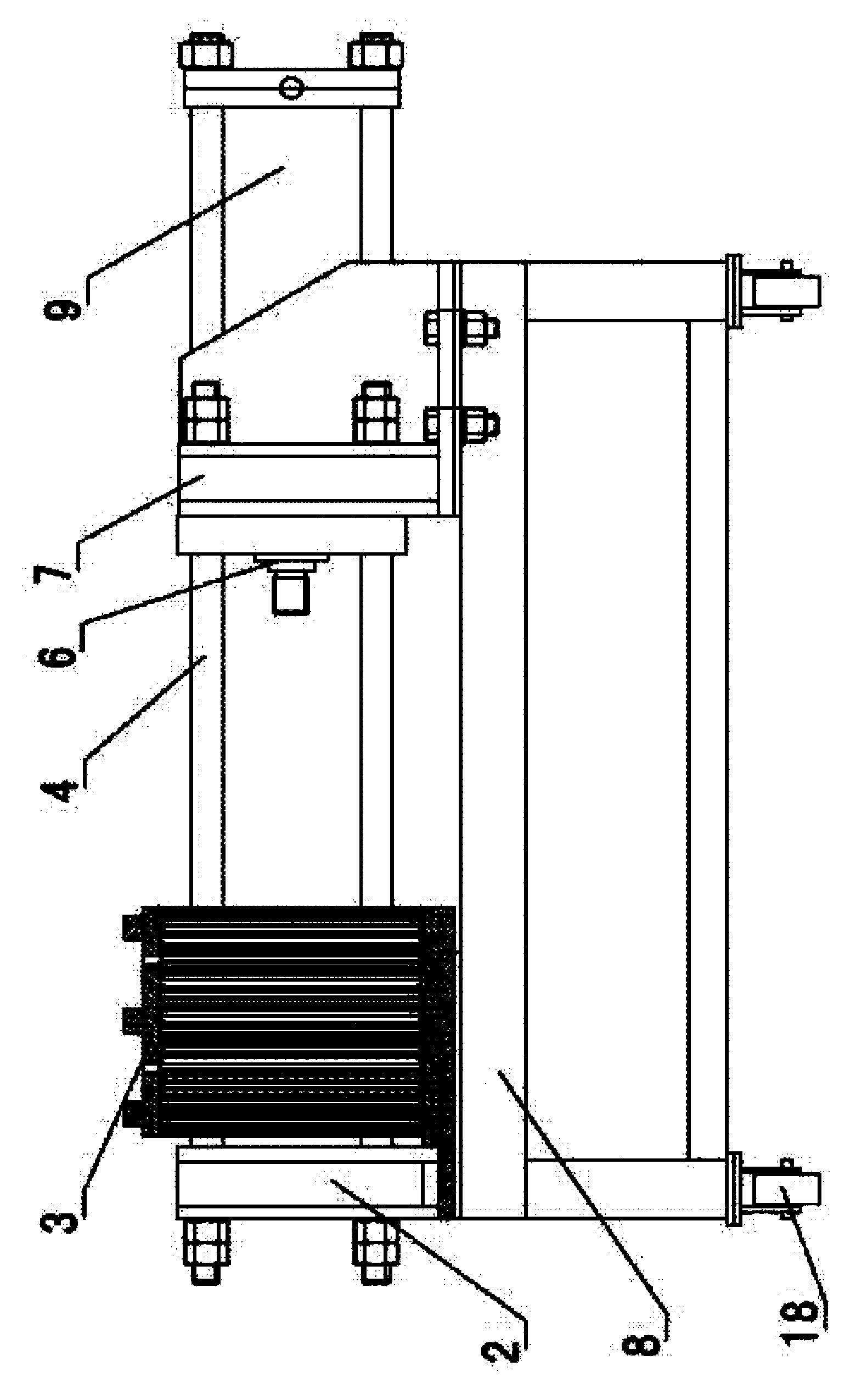
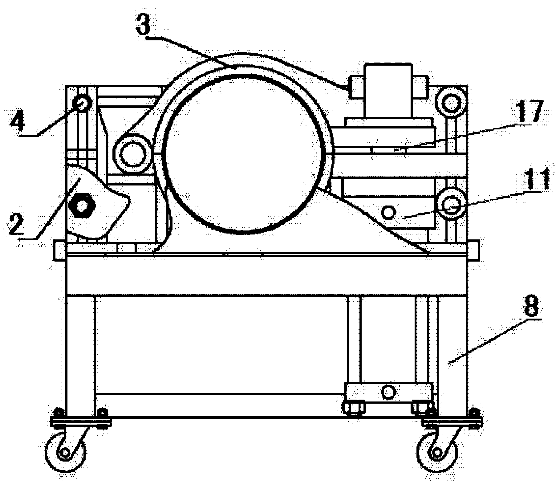
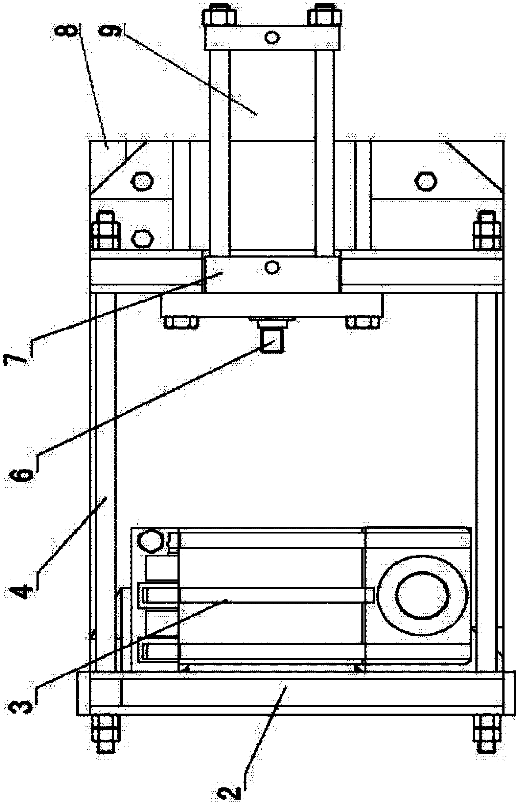
[0023] As shown in Figure l to image 3 A steel-plastic composite pressure pipe flaring machine shown is characterized in that it includes a frame 8, a flaring mechanism horizontally arranged above the end of the frame 8, and a clamping mechanism vertically arranged at the other end of the frame 8 and a control system; the flaring mechanism includes a flaring drive device horizontally fixed on the top of the frame 8 and a profiling indenter 5 located at the output end of the flaring drive device; The clamping drive device at the end of the frame 8 and the split ring clamp fixedly arranged above the frame 8; the axis of the ring clamp coincides with the axis of the p...


PUM


Abstract

The invention provides a flaring machine of a plastic-steel-plastic composite pressure pipe. The flaring machine of the plastic-steel-plastic composite pressure pipe comprises a rack, a flaring mechanism, a clamping mechanism and a control system, wherein the flaring mechanism is horizontally arranged above one end of the rack; the clamping mechanism is vertically arranged at the other end of the rack; the flaring mechanism comprises a flaring driving device and a profiling pressure head, wherein the flaring driving device is horizontally and fixedly arranged above the rack; the profiling pressure head is arranged on the output end of the flaring driving device; the clamping mechanism comprises a clamping and driving device and a separated-type annular fixture, wherein the clamping and driving device is vertically and fixedly arranged on one end of the rack; the separated-type annular fixture is fixedly arranged above the rack; the axis of the annular fixture is coincided with the axis of the profiling pressure head; the inner surface of the annular fixture is provided with annular inverted teeth which are distributed uniformly along the axis direction. The device is used for flaring the end opening of the plastic-steel-plastic composite pressure pipe by using a hydraulic device and the profiling pressure head, so that the working intensity of construction personnel is reduced; because the hydraulic device and the profiling pressure head are adopted for flaring, and consumable parts are not adopted for the device, the continuous operation capability of the device is improved, and the installation and construction efficiencies of the plastic-steel-plastic composite pressure pipe are improved.

Description

technical field [0001] The invention relates to an auxiliary installation device for a steel-plastic composite pressure pipe, in particular to a belling machine for a steel-plastic composite pressure pipe. Background technique [0002] The steel-plastic composite pressure pipe industry is an emerging industry that has just developed in recent years. It is favored by many manufacturers and users because of its high pressure bearing capacity, low price, good corrosion resistance, and small linear expansion coefficient. . Flared pipe fittings for steel-plastic composite pressure pipes have the characteristics of high reliability and high pressure bearing capacity among the various types of pipe fittings used in steel-plastic composite pressure pipes, and are widely used in the connection of steel-plastic composite pressure pipes. [0003] At present, the connection tools used for the connection of steel-plastic composite pressure pipe flared pipe fittings include manual mechan...

Claims


Application Information

Patent Timeline
Patent Type & Authority Applications(China)
IPC IPC(8): B29C57/04
Inventor 徐新
Owner NINGBO KANGRUN MACHINERY TECH
Why Eureka
Try Eureka