Stabilizer bar device of automobile
A technology of stabilizer bar and stabilizer bar bushing is applied in the directions of vehicle components, transportation and packaging, interconnection systems, etc., and can solve the problems of the negative impact of the balance effect of the stabilizer bar device, the energy loss of the stabilizer bar body, and the complex structure of the stabilizer bar body. , to reduce the risk of interference, light weight and compact structure
- Summary
- Abstract
- Description
- Claims
- Application Information
AI Technical Summary
Problems solved by technology
Method used
Image

Examples
Embodiment 1
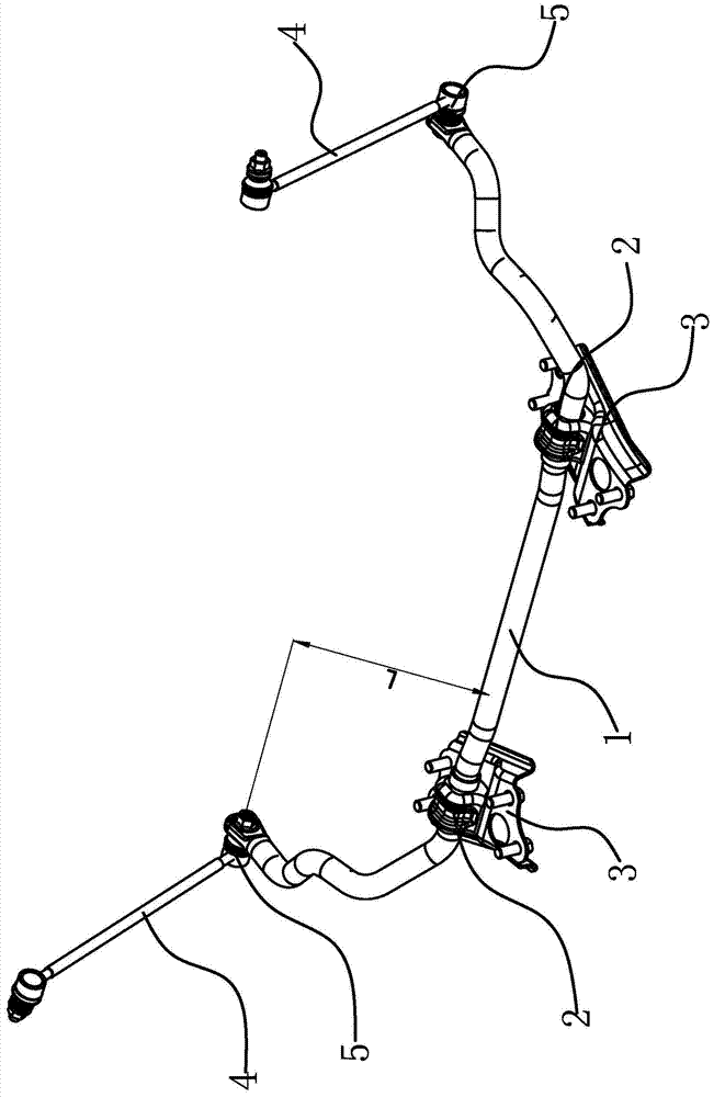
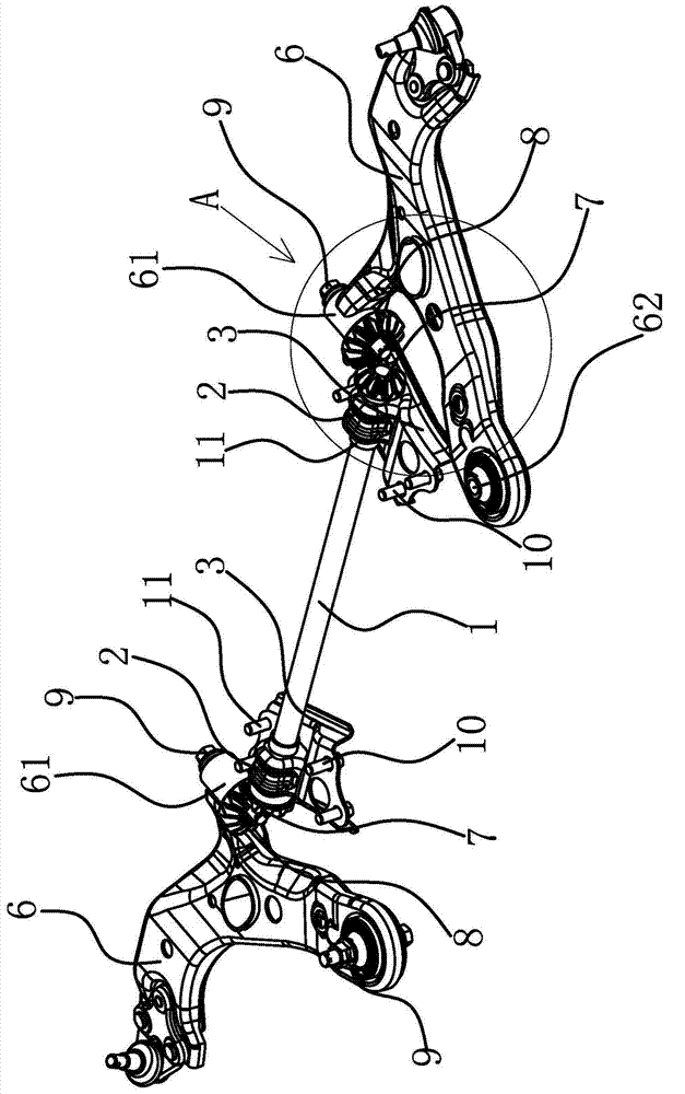
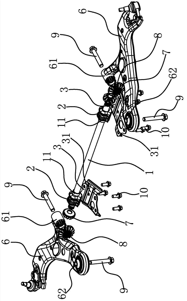
[0029] The stabilizer bar device of the automobile is arranged between the auxiliary vehicle body and the lower swing arm assembly 6, and is used to realize the balance effect on both sides of the automobile body when the automobile is running or turning. like image 3 As shown, the lower swing arm assembly 6 has a mounting hole 1 62 and a mounting hole 2 63. The mounting hole 1 62 and the mounting hole 63 are respectively connected to the sub-frame through mounting screws. The lower swing arm assembly 6 can be connected to the sub-frame. swing. The stabilizer bar device of this automobile comprises stabilizer bar body 1, stabilizer bar bushing 2, stabilizer bar support 3, bevel gear one 7 and bevel gear two 8.
[0030] Specifically, as figure 2 and image 3 As shown, the stabilizer bar body 1 is a straight rod, and in this embodiment, the stabilizer bar is made of spring steel. The stabilizer bar body 1 is installed on the sub-frame through the stabilizer bar bushing 2 a...
Embodiment 2
[0036] The technical solution in this embodiment is basically the same as the technical solution in Embodiment 1, the difference is that in this embodiment, the bevel gear 7 has a central hole, and the bevel gear 7 is sleeved on the stabilizer bar body 1 through the central hole. The center hole is provided with a card slot along the circumference, and the outer surface of the stabilizer bar body 1 has a buckle that matches the card slot. The bevel gear 7 passes the buckle and the card The groove fits with the axial positioning of the stabilizer bar body 1 . When assembling, the internal spline in the central hole of the bevel gear 7 cooperates with the external spline at the end of the stabilizer bar body 1. When the bevel gear 1 7 moves axially to the designed position, the buckle on the stabilizer bar body 1 snaps into place. In the draw-in groove on the bevel gear, the bevel gear one 7 and the stabilizer bar body 1 are positioned.
PUM
 Abstract
Description
Claims
Application Information