valve timing controller
A controller and valve timing technology, applied in valve devices, machines/engines, engine components, etc., can solve problems such as unrestricted oil pressure and leakage
- Summary
- Abstract
- Description
- Claims
- Application Information
AI Technical Summary
Problems solved by technology
Method used
Image

Examples
no. 1 example
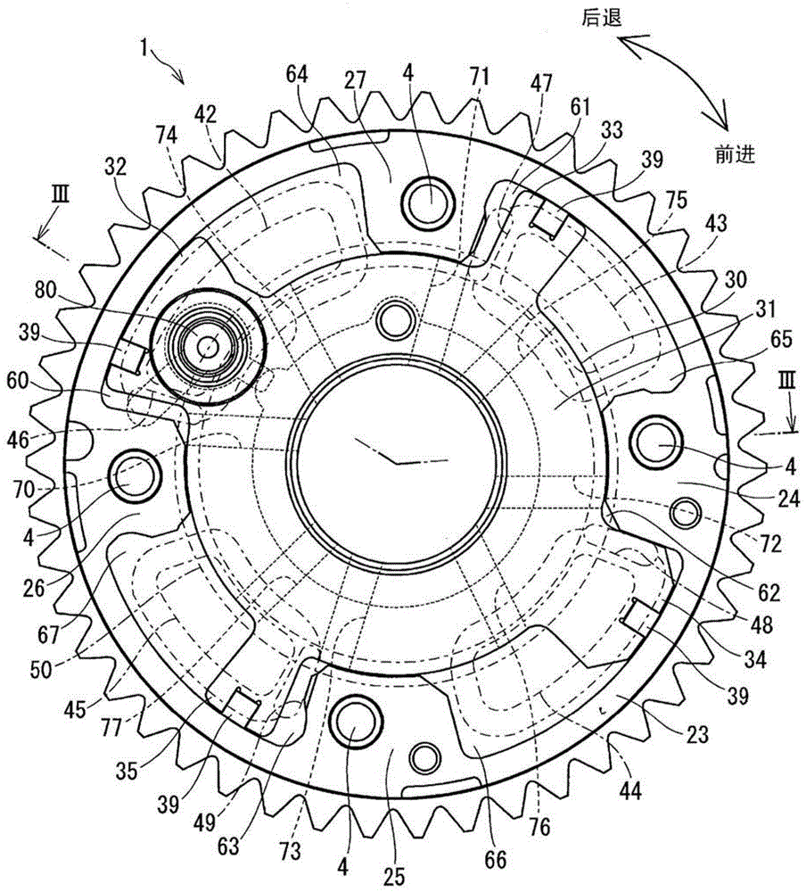
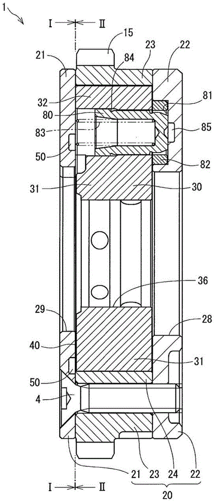
[0022] will refer to Figure 1 to Figure 6 The first embodiment is described. Valve timing controller 1 for Figure 5 In the drive train of internal combustion engine 10 is shown. In the transmission system, a gear 12 is fixed to a crankshaft 11 (drive shaft) of an engine 10, and gears 15 and 16 are fixed to two camshafts 13 and 14 (driven shafts), respectively. A chain 17 is linked with gears 12 , 15 , 16 and torque is transmitted from crankshaft 11 to camshafts 13 and 14 . Camshaft 13 drives discharge valve 18 and camshaft 14 drives suction valve 19 . In the valve timing controller 1 , the gear 16 is connected to the chain 17 , and the vane rotor 30 is connected to the camshaft 14 . The valve timing controller 1 controls the opening and closing timing of the suction valve 19 by rotating the crankshaft 11 and the camshaft 14 with a predetermined phase difference. exist Figure 5 , the valve timing controller 1 rotates clockwise in the direction of rotation.
[0023] Su...
no. 2 example
[0058] will refer to Figure 7 A second embodiment is described. In each of the following embodiments, some parts and components that are substantially the same as those in the first embodiment are denoted by the same reference numerals, and the same description will not be repeated.
[0059] Figure 7 The front plate 21 of the valve timing controller is shown. exist Figure 7 In , alternate long and short dash lines show the position of the sealing plate 40 .
[0060] In the second embodiment, the front plate 21 has oil pressure grooves 511-514 at positions corresponding to the seal members 42-45 of the seal plate 40, respectively. The oil pressure grooves 511 - 514 respectively overlap with a part of the openings 46 - 49 of the sealing plate 40 , and extend in an arc shape in the circumferential direction within a range corresponding to the sealing members 42 - 45 . The oil pressure grooves 511-514 may extend in a straight shape instead of an arc.
[0061] In the secon...
no. 3 example
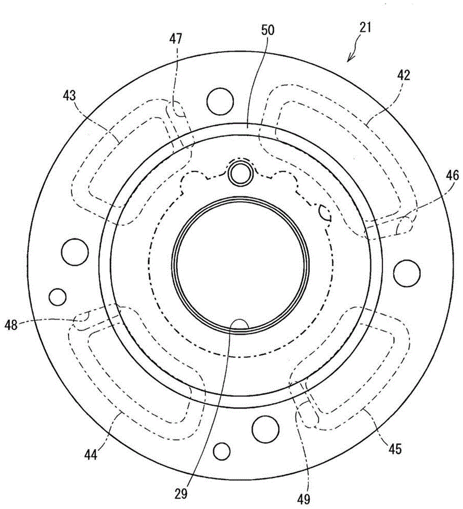
[0063] will refer to Figure 8 A third embodiment is described. Figure 8 The front plate 21 of the valve timing controller is shown. exist Figure 8 In , alternate long and short dash lines show the position of the sealing plate 40 .
[0064] In the third embodiment, the front plate 21 has oil pressure grooves 521-524 at positions corresponding to the seal members 42-45 of the seal plate 40, respectively. The oil pressure grooves 521 - 524 are defined in almost the same range as the seal members 42 - 45 of the seal plate 40 , or the oil pressure grooves 521 - 524 are defined to cover all the seal members 42 - 45 of the seal plate 40 .
[0065] In the third embodiment, the pressure drop of the back pressure chamber 90 can be reduced as a whole. Therefore, all the back pressure chambers 90 can be quickly filled with oil pressure from the openings 46 - 49 of the sealing plate 40 .
PUM
 Abstract
Description
Claims
Application Information
 - R&D
- Intellectual Property
- Life Sciences
- Materials
- Tech Scout
- Unparalleled Data Quality
- Higher Quality Content
- 60% Fewer Hallucinations
Browse by: Latest US Patents, China's latest patents, Technical Efficacy Thesaurus, Application Domain, Technology Topic, Popular Technical Reports.
© 2025 PatSnap. All rights reserved.Legal|Privacy policy|Modern Slavery Act Transparency Statement|Sitemap|About US| Contact US: help@patsnap.com