Device for realizing incompressible fluid critical flow by applying mechanical choking principle

A technology of compressing fluid and critical flow, applied in the direction of fluid flow, mechanical equipment, etc., can solve the problems affecting flow control and measurement accuracy, no shielding effect, poor safety performance, etc., to achieve small energy loss, obvious effect, and reduce erosion. Effect

Inactive Publication Date: 2014-02-12
XI AN JIAOTONG UNIV
View PDF4 Cites 14 Cited by
  • Summary
  • Abstract
  • Description
  • Claims
  • Application Information

AI Technical Summary

Problems solved by technology

However, this congestion method has obvious shortcomings such as huge energy loss, high noise, poor safety performance, and no shielding effect on upstream pressure disturbances, which affects flow control and measurement accuracy.
T

Method used


Image

  • Device for realizing incompressible fluid critical flow by applying mechanical choking principle
  • Device for realizing incompressible fluid critical flow by applying mechanical choking principle
  • Device for realizing incompressible fluid critical flow by applying mechanical choking principle

Examples


Embodiment 1

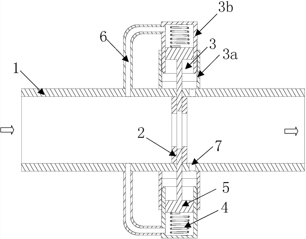
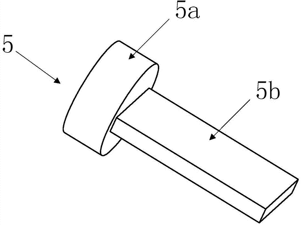
[0031] like figure 1 As shown, the present embodiment is a device for realizing the critical flow of incompressible fluid by applying the principle of mechanical choking, including a cylindrical shell 1, and a special-shaped orifice plate 2 is coaxially fixed in the cylindrical shell 1, and the two can Use any kind of fixed connection such as welding or screw connection. Two spring-float action chambers 3 are arranged symmetrically up and down at the position corresponding to the special-shaped orifice plate 2 outside the cylindrical shell 1, and a connected high-precision linear spring 4 and float 5 are arranged in the spring-float action chamber 3 , the upper cavity of the spring-float action chamber 3 communicates with the upstream pipeline of the special-shaped orifice plate 2 through the high-pressure guide channel 6, and the lower cavity communicates with the downstream pipeline of the special-shaped orifice plate 2 through the low-pressure guide hole 7. The high-pressu...

Embodiment 2

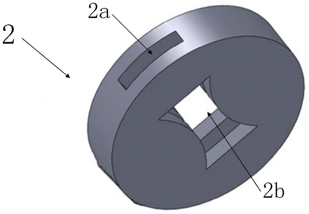
[0042] like Image 6 As shown, it is another structural form of the present invention that applies the principle of mechanical choking to realize the critical flow of incompressible fluid, wherein there is one spring-float action chamber 3, which is arranged on one side of the cylindrical shell 1, and the special-shaped orifice plate 2 A radial non-penetrating baffle guide hole 2a is opened at its axial middle position, and the section of the inner hole 2b corresponding to the baffle guide hole 2a is a quadrilateral with a specific shape, and the quadrilateral is an axisymmetric figure. The equation of its effective control shape line S is (2):

[0043] y = Q 4 α 2 ρk / A 0 ( m - x ...


PUM


Abstract

The invention discloses a device for realizing incompressible fluid critical flow by applying the mechanical choking principle. The device comprises a cylindrical shell, wherein an irregularly-shaped hole plate is coaxially fixed in the cylindrical shell, a long slot is formed along the circumferential direction of the cylindrical shell, an inner hole and a spoiler guide hole are formed in the irregularly-shaped hole plate, the end face of the long slot is aligned at the end face of the spoiler guide hole, a spring-float acting chamber is arranged outside the cylindrical shell, a high precision linear spring and a float which are connected are arranged in the spring-float acting chamber, the float can perform free sliding in a guide channel formed by the long slot and the spoiler guide hole, an upper cavity of the spring-float acting chamber is communicated with a pipeline at the upstream of the irregularly-shaped hole plate through a high pressure guide channel, a lower cavity of the spring-float acting chamber is communicated with a pipeline at the downstream of the irregularly-shaped hole plate through a low pressure guide hole, thus an additional throttling element similar to the cavitation barrier layer in the traditional incompressible fluid critical flow device can be formed. The device has the advantages of low velocity of flow, small pressure loss, good safety performance, and capability of maintaining the incompressible fluid critical flow during the upstream and downstream pressure fluctuation.

Description

technical field [0001] The invention belongs to the technical field of fluid control and measurement, and in particular relates to a device for realizing the critical flow of incompressible fluid by applying the principle of mechanical blockage. Background technique [0002] The so-called critical flow means that under certain inlet parameters, when the downstream pressure of the critical flow device reaches a certain critical value, the flow rate will reach a maximum value. If the outlet pressure is further reduced, the flow rate will remain constant. It will not increase with the decrease of downstream pressure, at this time, the flow is also said to reach a choked state. In the congested state, the interference downstream of the device is completely blocked, and the flow rate can always remain highly constant. [0003] Critical flow phenomena can occur in both gas flows and liquid flows. In gas flow, when the flow velocity at the throat of the Venturi nozzle reaches the...

Claims


Application Information

Patent Timeline
IPC IPC(8): F15D1/06
Inventor 张兴凯王栋史红卫王帅张炳东
Owner XI AN JIAOTONG UNIV
Why Eureka
Try Eureka