Comfortable jaw clutch

A clutch and claw technology, applied in the field of comfortable claw clutches

Active Publication Date: 2014-02-12
HOERBIGER ANTRIEBSTECHN HLDG +1
View PDF5 Cites 6 Cited by
  • Summary
  • Abstract
  • Description
  • Claims
  • Application Information

AI Technical Summary

Problems solved by technology

In principle, there is the problem that the claw clutches can only be shifted if there is no or only a small rotational speed difference between the meshing components
The disadvantage of the syn

Method used


Image

  • Comfortable jaw clutch
  • Comfortable jaw clutch
  • Comfortable jaw clutch

Examples


Embodiment Construction

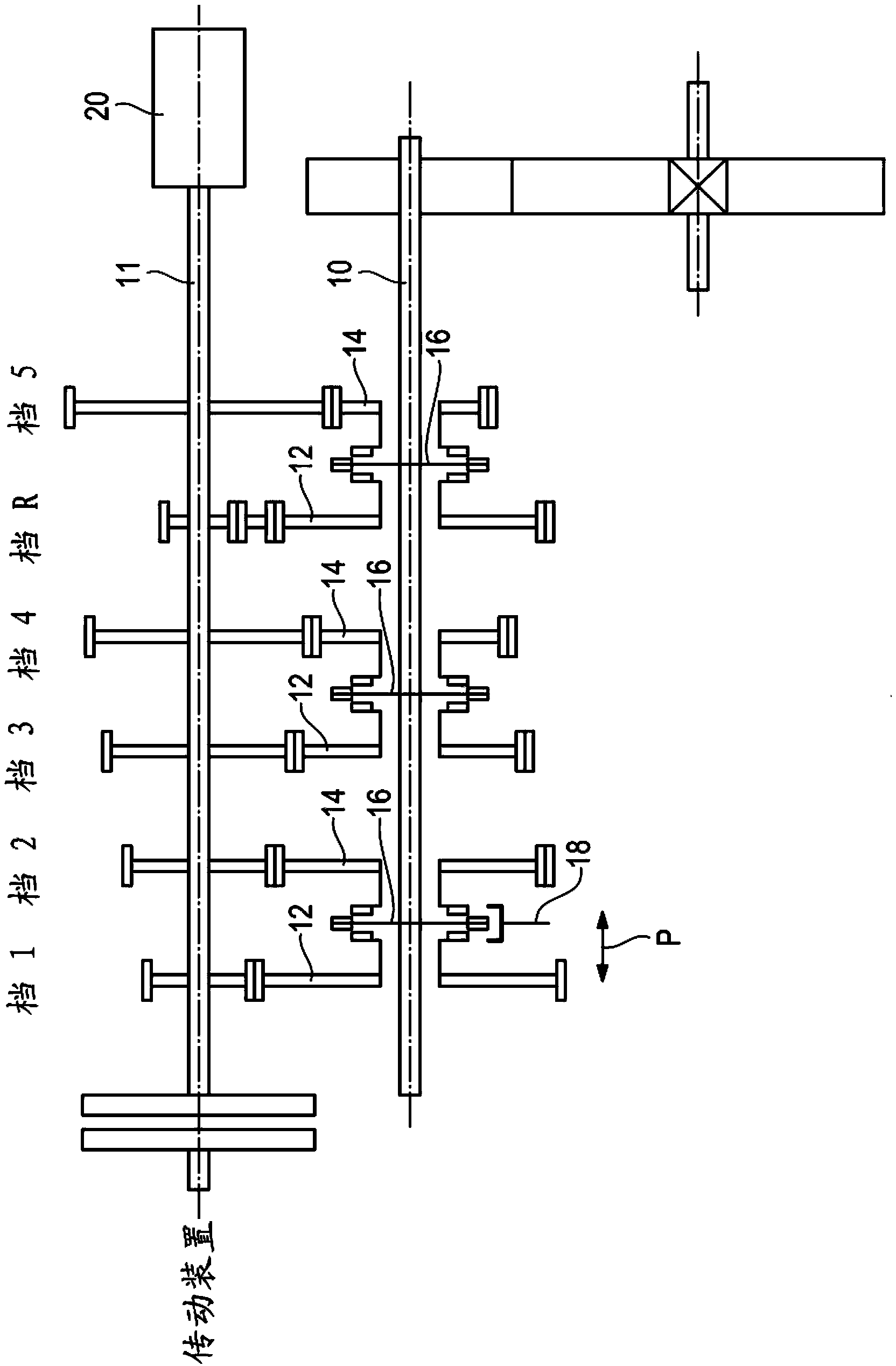
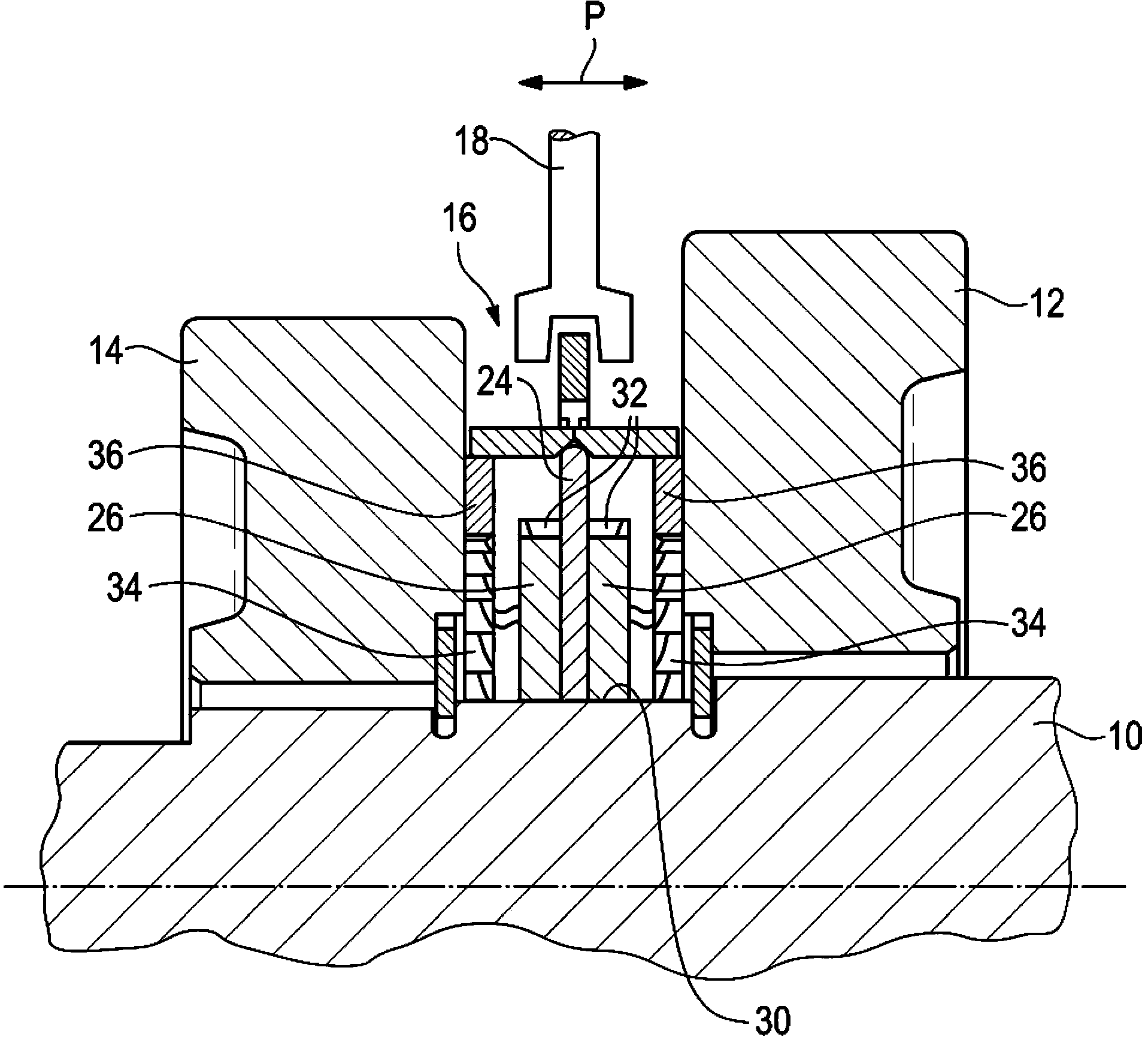
[0028] exist figure 1 A transmission shaft 10 of the transmission is shown in , on which two output wheels 12 , 14 are arranged. The driven wheels 12 , 14 are mounted rotatably in the circumferential direction on the transmission shaft 10 . The other driven wheels meshing with the driven wheels 12 , 14 , which are arranged on the second transmission shaft, are shown here for the sake of clarity as few as the other driven wheel pairs and the rest of the gearbox.

[0029] Between the two driven wheels 12 , 14 is arranged a transmitter 16 which can be shifted in one or the other direction (see arrow P) by means of a shift fork 18 in order to make the two driven wheels One or the other of 12 , 14 is coupled to the transmission shaft 10 in a torque-proof manner.

[0030] In addition, in figure 1 Also shown schematically is an electric motor 20 with which the rotational speed of the second transmission shaft 11 can be brought to a defined value. On the second transmission shaft,...


PUM


Abstract

The invention relates to a jaw clutch transmitter for a transmission, which includes a transmitter body, at least one torque transmission element which is connected to the transmitter body in a torsion-proof manner and is displaceable in the axial direction of a transmission shaft, and at least one clutch formation which is connected to the transmitter body in a torsion-proof manner and can be brought into engagement with a complementary driven wheel clutch formation of a gear wheel,and at least one slotted friction ring is provided which can be brought into engagement with the friction surface associated with the driven wheel. The invention also relates to a gearbox with at least one transmission shaft, at least one jaw clutch transmitterwhich is arranged displaceably on the transmission shaft, and at least one driven wheel provided with a driven wheel clutch formation which is engageable to the clutch formation on the transmitte, whereby the driven wheel is coupled with the transmission shaft in a torsion-proof manner, and the driven wheel is provided with a friction surface which can cooperate with the friction ring of the transmitter.

Description

technical field [0001] The invention relates to a claw clutch transmitter for a gearbox having a transmitter body, at least one torque transmission element and at least one clutch configuration (Kupplungsgestaltung), the at least one torque transmission element being torque resistant Way (drehfest) connected to the transmitter body and displaceable in the axial direction on the transmission shaft, said at least one clutch configuration is connected to the transmitter body in a torque-resistant manner and can be connected with a complementary driven wheel of the driven wheel The clutch configuration is engaged. The invention also relates to a gearbox having such a claw clutch transmitter. Background technique [0002] A pawl clutch is a detachable connection between two components, one of which (the pawl) is mostly adjustable in the axial direction and can be brought into mesh with the second component (the counter pawl). In this way, torque transmission is possible by posi...

Claims


Application Information

Patent Timeline
IPC IPC(8): F16D11/16
CPCF16D11/00F16D21/04F16D23/025F16D23/04
Inventor 奥特马尔·巴克米夏埃尔·克尔策
Owner HOERBIGER ANTRIEBSTECHN HLDG
Why Eureka
Try Eureka