A high-speed track state detection method based on line array and area array dual image acquisition channels

A high-speed track and state detection technology, applied in the field of machine vision and intelligent rail transit detection, can solve the problems of characteristic target recognition interference, difficulty in completing real-time detection, and huge real-time data stream of linear array CCD, so as to improve detection accuracy and rapid identification Positioning, the effect of high horizontal resolution

Active Publication Date: 2015-11-25
安捷光通科技成都有限公司
View PDF5 Cites 0 Cited by
  • Summary
  • Abstract
  • Description
  • Claims
  • Application Information

AI Technical Summary

Problems solved by technology

In the detection of the wear state of catenary or track, because the characteristics of the wear state are weak, a line array CCD camera with high resolution and high sampling speed is generally used for image acquisition, which will face two technical problems in practical application: (1) line array CCD camera The real-time data flow of the array CCD is very large, it is difficult to complete real-time detection, and the redundant data will interfere with the identification of the characteristic target; (2) In the actual train environment, there are interference factors such as changing illumination and vehicle body vibration, and the line array camera does not have Adaptability, it is difficult to guarantee the algorithm recognition effect
Therefore, although there are many researches on visual inspection for image processing, it is difficult to overcome the influence of complex illumination and strong jitter in the inspection environment in practical applications, and there is still a big gap from engineering applications.

Method used


Image

  • A high-speed track state detection method based on line array and area array dual image acquisition channels
  • A high-speed track state detection method based on line array and area array dual image acquisition channels
  • A high-speed track state detection method based on line array and area array dual image acquisition channels

Examples


Embodiment Construction

[0019] The specific implementation of the present invention will be further described below in conjunction with the accompanying drawings. However, it should be emphasized that the following embodiments are only exemplary and not intended to limit the scope and application of the present invention.

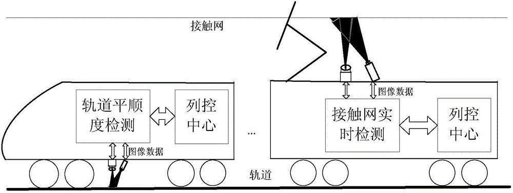
[0020] figure 1 Taking catenary and rail state detection as an example, it is a schematic diagram of the real-time image acquisition and processing scheme designed by the present invention. The image acquisition scheme is a combination of line-scan camera (1-DCCD) and area-scan camera (2DCCD). Catenary wear cross-section, rail cross-section, etc.) for image sampling. The spectral sensitivity of the area array camera and the linear array CCD is similar to ensure that the two have the same gray value distribution for the same lighting conditions.

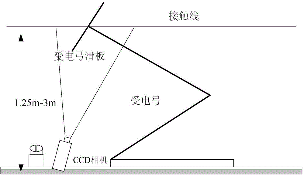
[0021] figure 2 Taking the catenary as an example, it is a schematic diagram of the camera installation scheme for state detection ...


PUM


Abstract

The invention discloses a high-speed track state detecting method based on a linear-array planar-array double image acquiring channel. The high-speed track state detecting method is used for carrying out image processing detecting for the track state based on an implementation platform consisting of a planar-array image acquiring processing system which is composed of a planar-array camera and an image processing module, a linear-array image acquiring processing system which is composed of a linear-array camera and the image processing module, an inter-module communication system and a comprehensive data processing terminal. The high-speed track state detecting method disclosed by the invention adopts an image acquiring structure which is combined with the linear-array camera and the planar-array camera, so that on one hand, redundant data of an area outside a target in a linear-array image is effectively eliminated, and on the other hand, real-time illumination information can provide information guide for the array image identification, so that accuracy for threshold value judgment and characteristic identification is improved, and therefore, real-time performance and robustness of algorithm identification are improved.

Description

technical field [0001] The invention relates to the fields of intelligent rail transit detection, machine vision, etc., improves the real-time image acquisition structure scheme of the detection target, combines the high coverage rate of the area array camera and the high sampling speed of the line array camera, as a method to improve the real-time vision based on image processing The key technology of detection. Background technique [0002] The rail transit state detection method based on image processing is a non-contact detection method. The mechanical characteristics of the detection target are not destroyed during the detection process. The image information is intuitive and the degree of intelligence is high. It is a detection method with application potential. In the detection of the wear state of catenary or track, because the characteristics of the wear state are weak, a line array CCD camera with high resolution and high sampling speed is generally used for image ...

Claims


Application Information

Patent Timeline
Patent Type & Authority Patents(China)
IPC IPC(8): G01C11/00
CPCG01B11/00G01C11/02G01C11/12
Inventor 闫连山吴宗玲赵明杰熊如刚潘炜郭进罗斌张志勇
Owner 安捷光通科技成都有限公司
Why Eureka
Try Eureka