Liquid flow non-magnetic detector and detection method thereof

A magnetic detection device and liquid flow technology, applied in the direction of volume/mass flow generated by electromagnetic effects, can solve the problems of small application range, cost reduction, and good versatility, and achieve wide application range, cost reduction, and good versatility Effect

Active Publication Date: 2014-02-12
杭州绿鲸科技有限公司
View PDF4 Cites 12 Cited by
  • Summary
  • Abstract
  • Description
  • Claims
  • Application Information

AI Technical Summary

Problems solved by technology

[0003] The invention mainly solves the technical problems that the original flow non-magnetic measuring device has a small measuring distance, cannot be measured in a meter with a thick watch case, and has a small application range; it provides a liquid flow non-magnetic detecting device and a detection method thereof , the measurement distance is large, and there is no limit to the thickness of the case, no matter whether the case is thick or thin, flow measurement can be realized, and the application range is wide
[0004] The present invention simultaneously solves the technical problems that the original flow non-magnetic measuring device must use MSP430FW42X series single-chip microcomputers to realize flow measurement, which cannot be realized with other low-cost single-chip microcomputers, has high cost, and has limitations; provides a liquid flow non-magnetic detection device and its The detection method, the single-chip microcomputer used in it only needs to satisfy the timer capture function to realize the flow measurement, so it can be realized by a low-cost single-chip microcomputer, which effectively reduces the cost, has strong portability and good versatility

Method used


Image

  • Liquid flow non-magnetic detector and detection method thereof
  • Liquid flow non-magnetic detector and detection method thereof
  • Liquid flow non-magnetic detector and detection method thereof

Examples


Embodiment

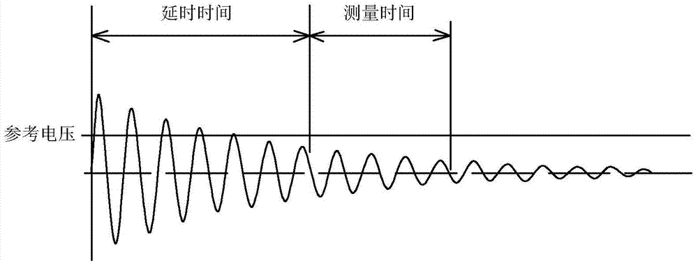
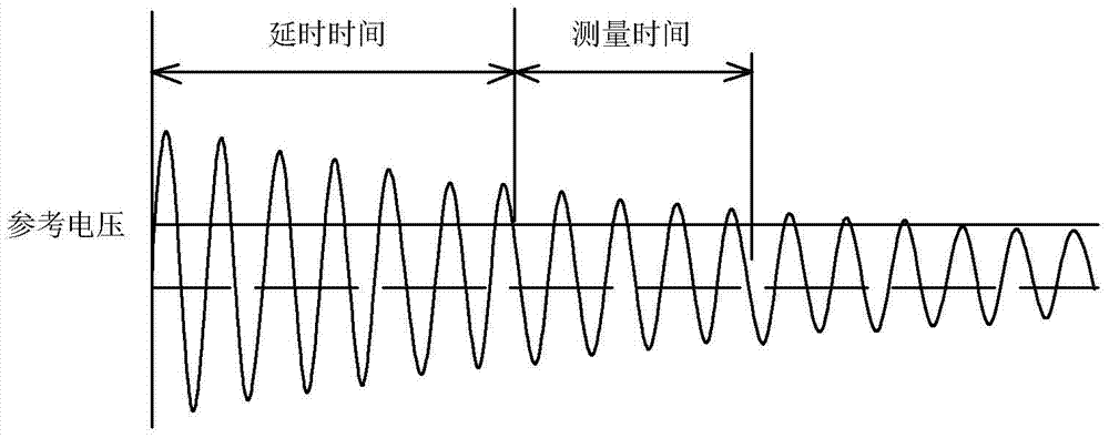
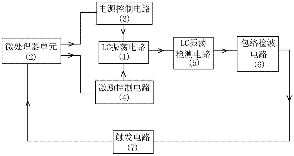
[0024] Embodiment: The liquid flow non-magnetic detection device of this embodiment, such as image 3 As shown, it includes LC oscillation circuit 1 , microprocessor unit 2 , power control circuit 3 , excitation control circuit 4 , LC oscillation detection circuit 5 , envelope detection circuit 6 and trigger circuit 7 . The first output end of the microprocessor unit 2 is connected with the input end of the power control circuit 3, the second output end of the microprocessor unit 2 is connected with the input end of the excitation control circuit 4, the power control circuit 3, the excitation control circuit 4 The output terminals are respectively connected to the two ends of the LC oscillation circuit 1, the oscillation output terminal of the LC oscillation circuit 1 is connected to the input terminal of the envelope detection circuit 6, and the output terminal of the envelope detection circuit 6 is connected to the input terminal of the trigger circuit 7 to trigger The outpu...


PUM


Abstract

The invention relates to a liquid flow non-magnetic detector and a detection method thereof. The detector comprises a microprocessor unit, a power supply control circuit and an excitation control circuit which are connected with the microprocessor unit, and an LC oscillating circuit, an LC oscillating detection circuit, an envelope detection circuit and a trigger circuit which are connected in sequence, wherein the output ends of the power supply control circuit and the excitation control circuit are respectively connected with two ends of the LC oscillating circuit, and the trigger circuit is connected with a timer capture input end of the microprocessor unit. The LC oscillating circuit is located above an impeller comprising an insulating area and a conducting area. The detection method comprises the steps that an oscillating wave output by the LC oscillating circuit is processed by the LC oscillating detection circuit, the envelope detection circuit and the trigger circuit and then is subjected to timer capture by the microprocessor unit, the position changes of the conducting area and the insulating area of the impeller are judged, and finally liquid flow is calculated. The measuring distance is larger, the application range is wide, the singlechip microcomputer selection limitation is less, the cost is reduced, and the universality is good.

Description

technical field [0001] The invention relates to a non-magnetic flow meter, in particular to a non-magnetic detection device for liquid flow and a detection method thereof. Background technique [0002] In the non-magnetic water meter, the MSP430FW427 single-chip microcomputer is mostly used to realize the flow detection at present, and the SCAN IF non-magnetic detection module is integrated inside the single-chip microcomputer. The SCAN IF non-magnetic detection module is a unique module of the MSP430FW42X series single-chip microcomputer launched by Texas Instruments. It can automatically detect linear or rotary motion at low power consumption, and is mainly used for heat meters, hot and cold water meters, and gas meters. And industrial flow meters and other instruments. In the existing non-magnetic water meter, the flow detection part is mainly composed of the SCAN IF non-magnetic detection module inside the microcontroller and two LC sensors connected externally. The LC ...

Claims


Application Information

Patent Timeline
IPC IPC(8): G01F1/56
Inventor 陈昌根周震宇孙锦山雷俊勇肖金凤吕善星陈熙俊
Owner 杭州绿鲸科技有限公司
Why Eureka
Try Eureka