Supercharge Your Innovation With Domain-Expert AI Agents!

Integrated optical module

一种集成型光、台座的技术,应用在光学、光导、光学元件等方向,能够解决发生损耗、光干涉回路特性恶化等问题

Active Publication Date: 2014-02-12
NIPPON TELEGRAPH & TELEPHONE CORP +1
View PDF5 Cites 2 Cited by
  • Summary
  • Abstract
  • Description
  • Claims
  • Application Information

AI Technical Summary

Problems solved by technology

Due to the change of the equivalent circuit length due to the change of the refractive index caused by the stress, the characteristics of the interferometer will be changed, so the characteristics of the optical interference circuit will be deteriorated.
[0014] In this regard, in order to suppress changes in optical characteristics by suppressing the occurrence of thermal stress, as the adhesive 18, if a soft adhesive such as an elastic adhesive or a paste is used, or a paste for fixing (for example, refer to Patent Document 1), the influence of the aforementioned optical axis shift will become significant, and loss will occur

Method used


Image

  • Integrated optical module
  • Integrated optical module
  • Integrated optical module

Examples


Embodiment Construction

[0043] Embodiments of the present invention will be described in detail below.

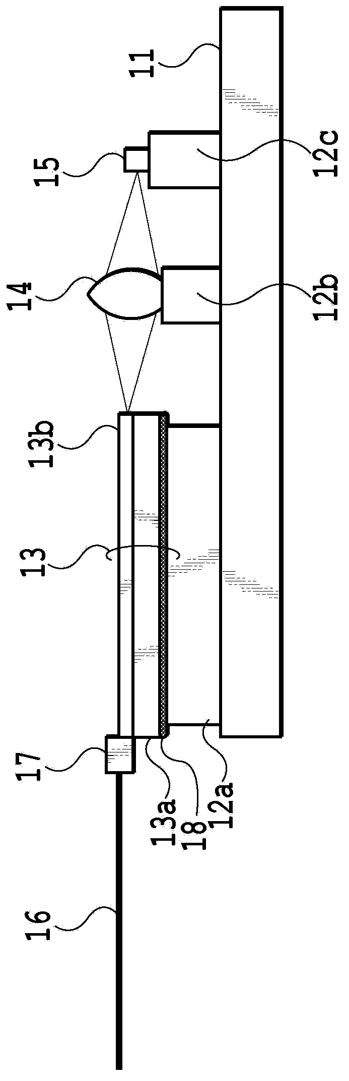
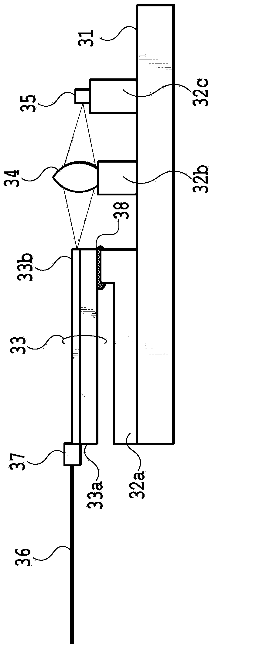
[0044] Figure 5A and 5B It is a figure which shows the main part of the integrated optical module of 1st Embodiment. Figure 5A It is a side sectional view showing the schematic structure of the main part of the integrated optical module of the first embodiment, Figure 5B It is a plan view of the bracket used for the integrated optical module of the first embodiment. The integrated optical module is composed of optical components such as PLC chips, lenses, light-receiving elements or light-emitting elements mounted on the base substrate through brackets, and sealed with packages. Formed the PLC chip 33 of optical interference circuit such as Figure 5A As shown, it is connected to the optical fiber 36 via the optical fiber fixing part 37, and is glued and fixed on the bracket 40 by an adhesive 38a.

[0045] The PLC chip 33 is formed by laminating a silica glass layer 33b on a Si substrate 3...


PUM


Abstract

The purpose of the present invention is to provide an integrated optical module wherein peeling is prevented and variations in the displacement of a PLC chip are prevented from occurring when humidity is changed. An integrated optical module provided with a PLC chip, a base adhered and secured to a portion of the bottom surface of the PLC chip by means of an adhesive agent coated on an adhering surface, and a support part for supporting the base, wherein a water-repellent treatment part in which the top surface of the support part is masked with a water-repellent material is provided. The water-repellent treatment part is only provided on a predetermined width in the periphery of the base. The water-repellent treatment part is provided on a width of 100 mum or more in the periphery of the base.

Description

technical field [0001] The present invention relates to an integrated optical module (Integrated Optical Module), which is integrated with a light-emitting element or a light-receiving element to form an optical transceiver and is loaded with a planar light wave circuit. Background technique [0002] With the progress of optical communication technology, the development of optical components becomes more and more important. In particular, optical transceivers are being studied to increase the transmission speed and response speed, and the communication capacity is expanding. The structure of a general transceiver is composed of a light-emitting element or a light-receiving element made of an optical semiconductor, and an optical fiber for output or input, and they are optically coupled through a lens. For example, in the case of an optical receiver, light emitted from an optical fiber at the input end is imaged by a lens onto a light receiving element, and directly detected...

Claims


Application Information

Patent Timeline
Patent Type & Authority Applications(China)
IPC IPC(8): G02B6/12G02B6/13
CPCG02B6/42G02B6/4266G02B6/30G02B6/4239G02B6/12G02B2006/12083
Inventor 笠原亮一荒武淳小川育生那须悠介铃木雄一相马俊一
Owner NIPPON TELEGRAPH & TELEPHONE CORP
Features
  • R&D
  • Intellectual Property
  • Life Sciences
  • Materials
  • Tech Scout
  • Unparalleled Data Quality
  • Higher Quality Content
  • 60% Fewer Hallucinations
Learn More