Shifting register circuit

A shift register and circuit technology, applied in static memory, digital memory information, instruments, etc., can solve the problem of reduced circuit driving ability

Active Publication Date: 2014-02-12
AU OPTRONICS CORP
View PDF6 Cites 3 Cited by
  • Summary
  • Abstract
  • Description
  • Claims
  • Application Information

AI Technical Summary

Problems solved by technology

Such an approach will reduce the driving

Method used


Image

  • Shifting register circuit
  • Shifting register circuit
  • Shifting register circuit

Examples


Embodiment Construction

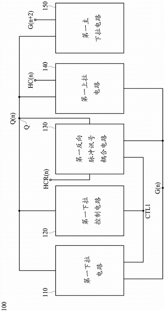
[0048] Please refer to" figure 1 "," figure 1 ” shows a block diagram of a shift register circuit according to an embodiment of the present invention. The shift register circuit 100 includes a first pull-down circuit 110 , a first pull-down control circuit 120 , a first inverted pulse signal coupling circuit 130 , a first pull-up circuit 140 and a first main pull-down circuit 150 . The first pull-up circuit 140 is used for receiving the first driving signal Q(n) and the first pulse signal HC(n) from the node Q to output the first gate control signal G(n). The first pull-down circuit 110, the first pull-down control circuit 120, the first inverted pulse signal coupling circuit 130, the first pull-up circuit 140 and the first main pull-down circuit 150 are all electrically connected to the node Q, and the first down The pull-up circuit 110 , the first inverted pulse signal coupling circuit 130 and the first pull-up circuit 140 are used to control the output waveform of the fir...


PUM


Abstract

The invention discloses a shifting register circuit comprising a pull-down control circuit, a pull-down circuit, a pulse inversion signal coupling circuit, a main pull-down circuit, and a pull-up circuit. The pull-down control circuit is electrically connected with the pull-down circuit and the pulse inversion signal coupling circuit. The pull-down circuit is electrically connected with the pull-up circuit by a driving signal and a grid electrode signal. The main pull-down circuit is electrically connected with the pull-up circuit, and the pull-up circuit is connected with a pulse signal and the driving signal to output a grid control signal. The pulse inversion signal coupling circuit can be used to output the pulse inversion signal to offset the surge of the driving signal timely.

Description

technical field [0001] The invention relates to a shift register structure applied in a display device; in particular, it relates to a shift register with automatic compensation function applied in a display device. Background technique [0002] With the increasing technology of the panel industry, customers have higher and higher demands on the panel, especially the width of the frame is an important indicator, and from the perspective of the enterprise, of course, it is also hoped that under the same functional conditions , the lower the production cost, the better. Based on the above two conditions, GOA (Gate Driver on Array) gradually replaces the function of the shift register in the traditional gate driver integrated circuit. In the current GOA circuit architecture, there is a Q signal inside to drive the shift register. Since this signal is an internal signal of the circuit, the corresponding resistor-capacitor (RC) load is relatively small, so it is susceptible to in...

Claims


Application Information

Patent Timeline
IPC IPC(8): G09G3/20G11C19/28
CPCG11C19/28G09G3/20G09G2310/0286
Inventor 林炜力张竣桓董哲维侯淑方
Owner AU OPTRONICS CORP
Why Eureka
Try Eureka