
Distributed battery management system and method for distributed battery management

A battery management system and battery management technology, applied in battery circuit devices, current collectors, electric vehicles, etc., can solve problems such as communication obstacles of subordinate control departments, and achieve the effect of improving safety and reliability and saving manufacturing costs.

Active Publication Date: 2014-02-12
HYUNDAI MOBIS CO LTD
View PDF6 Cites 6 Cited by
  • Summary
  • Abstract
  • Description
  • Claims
  • Application Information

AI Technical Summary

Problems solved by technology

Hybrid vehicles or electric vehicles require motors or inverters, but noise generated from the motors or inverters can cause communication barriers between slave control units

Method used


Image

  • Distributed battery management system and method for distributed battery management
  • Distributed battery management system and method for distributed battery management
  • Distributed battery management system and method for distributed battery management

Examples


no. 1 example

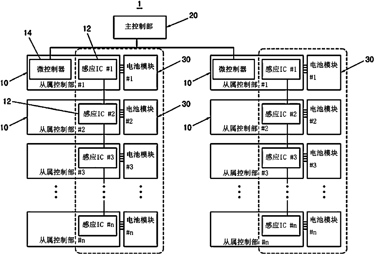
[0058] figure 1 It is a structural diagram of the distributed battery management system according to the first embodiment of the present invention, in which a plurality of slave control units 10 composed of two groups are shown. according to figure 1 , the distributed battery management system 1 of the first embodiment includes a plurality of slave control units 10 and a master control unit 20 composed of two groups, and each battery module 30 is connected to each corresponding plurality of slave control units 10 . Hereinafter, only the left group among the plurality of slave control units 10 will be described for convenience.

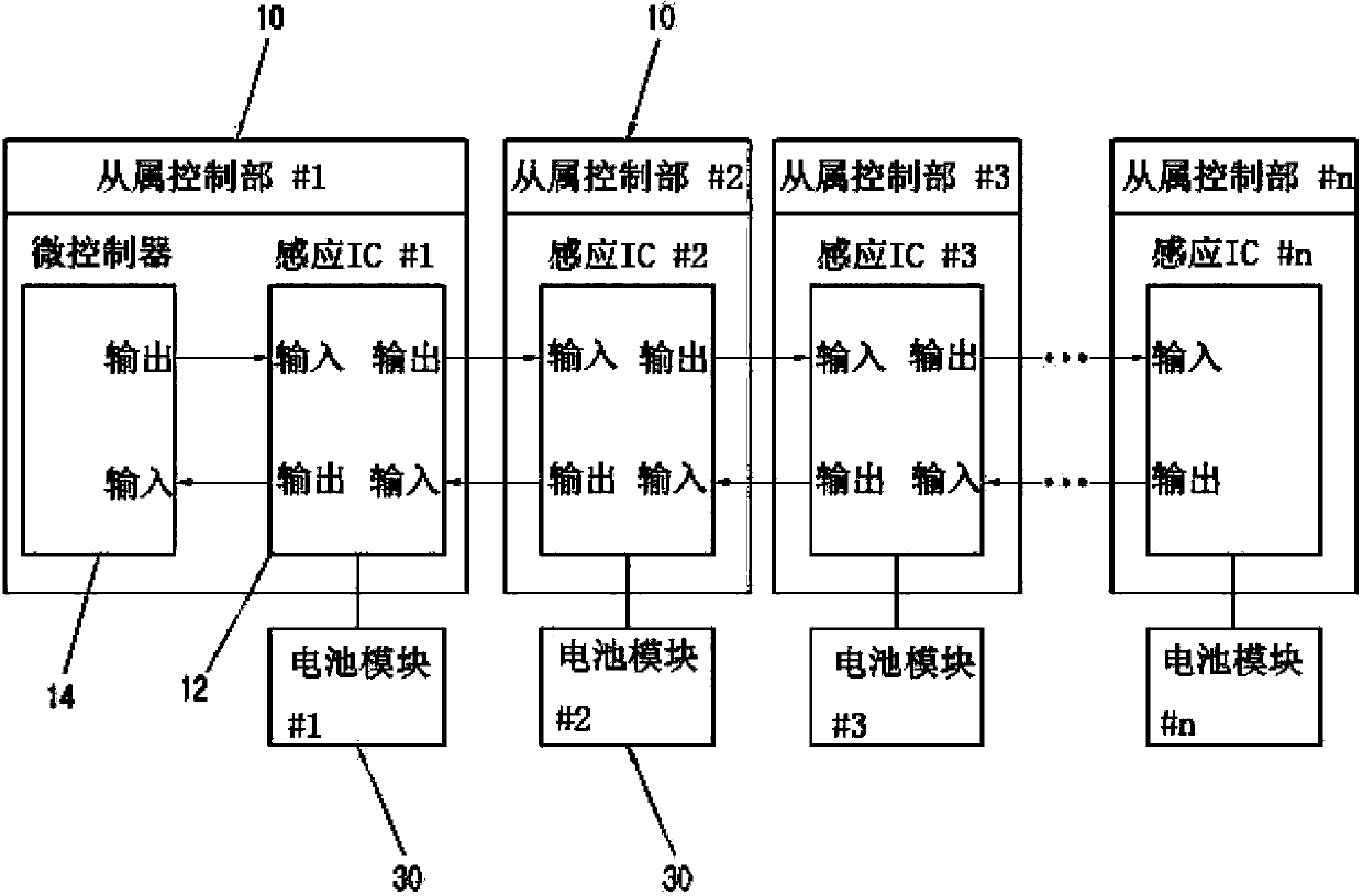
[0059] A plurality of slave control units 10 are arranged corresponding to the battery modules 30 respectively, and have a daisy chain structure in which the lowest slave control unit 10, #n to the highest slave control unit 10, #1 is connected in series.

[0060] figure 2 It is a configuration diagram of a plurality of slave control units in the f...

no. 2 example

[0079] Figure 7 It is a structural diagram of the distributed battery management system of the preferred second embodiment of the present invention.

[0080] according to Figure 7 , the distributed battery management system of the present invention includes encoding the control information transmitted by the master control unit 20 into an asynchronous differential signal, and decoding the differential signal corresponding to the sensing information encoded into the control information transmitted by each slave control unit 10 Interface IC100.

[0081] The highest-order slave control unit 10, #1 may include a microcontroller 200 in addition to the sensor IC 12. The microcontroller 200 receives the control information #1-#n used to control the operation of the slave control unit 10, and collects the sensing information #2-#n of a plurality of slave control units 10, #2-#n in the low order, and the sensing information #2-#n related to its own induction. Sensing information #...


PUM


Abstract

Disclosed is a distributed battery management system of managing a plurality of battery modules, including: slave controllers have a daisy chain structure in which the slave controllers are connected from a bottom-level slave controller up to a top-level slave controller in series, sequentially transfer control information received from the outside from the top-level slave controller up to the bottom-level slave controller, sense information on the battery modules in response to the transferred control information, sequentially transfer the sensed sensing information from the bottom-level slave controller up to the top-level slave controller, and transmit the sensing information transferred to the top-level slave controller to the outside; and a master controller which transmits the control information to the top-level slave controller among the slave controllers and manages the battery modules by using the sensing information received from the top-level slave controller.

Description

technical field [0001] The present invention relates to a distributed battery management system, in particular to a distributed battery management system using a main control unit and multiple slave control units to monitor battery modules. Background technique [0002] A distributed battery management system refers to a system that monitors the voltage and temperature of multiple battery modules and implements battery module control functions such as battery balancing. [0003] The distributed battery management system can be divided into master control part, block control part and slave control part. The slave control unit monitors information such as battery voltage and temperature of each battery module and transmits the information to the block control unit, and the block control unit transmits the battery module data transmitted by the slave control unit corresponding to its own block to the master control unit. [0004] The master control unit receives and processes ...

Claims


Application Information

Patent Timeline
Patent Type & Authority Applications(China)
IPC IPC(8): H02J7/00
CPCH02J1/10
Inventor 柳泳旭
Owner HYUNDAI MOBIS CO LTD
Learn More