Power supply circuit and power supply switching circuit of clock chip, power supply switching method and microwave oven

A clock chip, power supply circuit technology, applied in circuit devices, electrical components, emergency power supply arrangements, etc., can solve problems such as reducing battery life

Active Publication Date: 2014-02-12
GUANGDONG MIDEA KITCHEN APPLIANCES MFG CO LTD +1
View PDF3 Cites 8 Cited by
  • Summary
  • Abstract
  • Description
  • Claims
  • Application Information

AI Technical Summary

Problems solved by technology

However, the diode will cause a voltage drop of about 0.7V. When powered by a backup power supply, the actual input voltage value of the clock chip is only 2.3V. However, when the battery voltage drops to 2.5V or below, the clock chip can no longer work normally. As a result, it cannot supply power normally and will reduce the service life of the battery

Method used


Image

  • Power supply circuit and power supply switching circuit of clock chip, power supply switching method and microwave oven
  • Power supply circuit and power supply switching circuit of clock chip, power supply switching method and microwave oven
  • Power supply circuit and power supply switching circuit of clock chip, power supply switching method and microwave oven

Examples


Embodiment 1

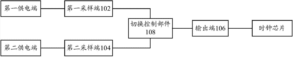
[0058] figure 1 A schematic structural diagram of a power supply switching circuit of a clock chip according to an embodiment of the present invention is shown.

[0059] Such as figure 1 As shown, the power supply switching circuit of the clock chip according to an embodiment of the present invention includes: a first sampling terminal 102 connected to the first power supply terminal, and the output of the first power supply terminal is obtained by converting an external AC signal The first DC voltage is sampled, wherein, the first power supply end is also connected to the power input end of the clock chip through a unidirectional conduction element; the second sampling end 104 is connected to the second power supply end, and the first power supply end is connected to the second power supply end. Sampling the second DC voltage output from the two power supply terminals and from the DC power supply, wherein the difference between the second DC voltage and the minimum operating...

Embodiment 2

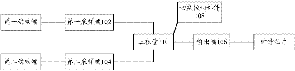
[0065] figure 2 A schematic structural diagram of a power supply switching circuit of a clock chip according to another embodiment of the present invention is shown.

[0066] Such as figure 2 As shown, the power supply switching circuit of the clock chip according to another embodiment of the present invention includes the first sampling terminal 102, the second sampling terminal 104, the output terminal 106 and the switching control unit 108 as described in the first embodiment, and A transistor 110 is also included.

[0067] Specifically, due to possible different types of the triode 110, the corresponding circuit structures and connection relationships are described below.

Embodiment approach 1

[0068] Embodiment 1: The transistor 110 is a PNP transistor.

[0069] The first sampling terminal 102 is connected to the base of the PNP transistor (not shown in the figure), the second sampling terminal 104 is connected to the emitter of the PNP transistor (not shown in the figure), the The output terminal 106 is connected to the collector of the PNP transistor (not shown in the figure), and the switching control part 108 compares the first DC voltage input to the base of the PNP transistor with the second DC voltage input to the emitter. DC voltage, when the first DC voltage is greater than the second DC voltage, disconnect the connection between the second power supply terminal and the power input terminal of the clock chip, and when the first DC voltage is less than the specified In the case of the second DC voltage, restore the connection between the second power supply terminal and the power input terminal of the clock chip, so that the clock chip can be powered by the ...


PUM


Abstract

The invention provides a power supply switching circuit of a clock chip. The power supply switching circuit comprises a first sampling terminal, a second sampling terminal, an output terminal and a switching control component, wherein the first sampling terminal is used for sampling a first direct current voltage; the second sampling terminal is used for sampling a second direct current voltage; the output terminal is connected to a power input terminal of the clock chip; the switching control component is used for comparing the first direct current voltage with the second direct current voltage and stopping or recovering connection between a second power supply terminal and the power input terminal of the clock chip. The invention further provides a corresponding power supply circuit of the clock chip, a microwave oven and a power supply switching method of the clock chip. By means of the technical scheme, different power sources can be used on different conditions, and the situation that the clock chip cannot be driven due to voltage drops can be avoided at the same time of ensuring that voltages of two power sources cannot flow backward mutually.

Description

technical field [0001] The invention relates to the technical field of power supply switching, in particular to a clock chip power supply switching circuit and a power supply switching method, a clock chip power supply circuit and a microwave oven. Background technique [0002] Also begin to install clock or perpetual calendar etc. on the electric appliance that people use daily, so that check time or date at any time. In the above-mentioned electrical appliances, such as microwave ovens, ovens, etc., the clock chip is directly powered by converting the mains power (alternating current) into direct current. However, when using mains power supply, if there is a power outage, the power plug falls off, etc., it may cause problems such as the need to reset the clock, causing inconvenience in use. [0003] In order to avoid frequent setting of the clock, you can consider setting up a backup power supply inside the electrical appliance, such as a button battery, so that after the...

Claims


Application Information

Patent Timeline
Patent Type & Authority Applications(China)
IPC IPC(8): H02J9/06
Inventor 姜大秉唐彬
Owner GUANGDONG MIDEA KITCHEN APPLIANCES MFG CO LTD
Why Eureka
Try Eureka