Stepping linear motor

A linear motor and rotor shaft technology, applied in electrical components, electromechanical devices, propulsion systems, etc., can solve the problems of low rotor machining accuracy, insufficient rotor strength, etc., which is beneficial to mass production and large inventory, and has good anti-rotation and stop performance. , The effect of high transmission efficiency

Active Publication Date: 2014-02-12
SHANGHAI MOONS ELECTRICAL APPLIANCE
View PDF4 Cites 13 Cited by
  • Summary
  • Abstract
  • Description
  • Claims
  • Application Information

AI Technical Summary

Problems solved by technology

Due to the fact that many through holes are punched around the shaft in this way, the strength of the rotor is not enough, and the machining accuracy of the rotor in the later stage is low.

Method used


Image

  • Stepping linear motor
  • Stepping linear motor
  • Stepping linear motor

Examples


Embodiment Construction

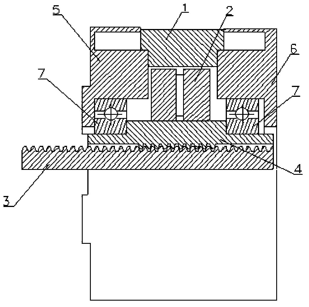
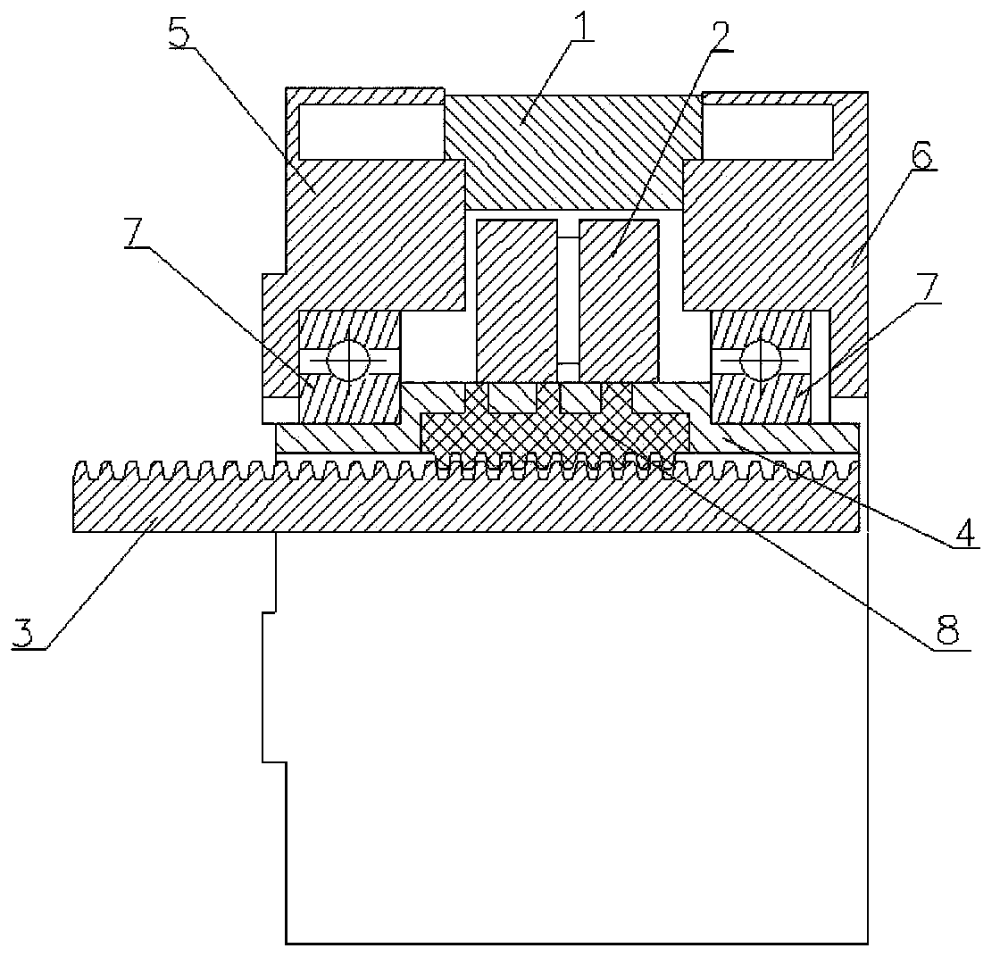
[0019] see Figure 7 , The stepping linear motor of the present invention comprises a stator 1, a rotor 2, a screw rod 3, a rotor shaft 4, a left end cover 5, a right end cover 6, a bearing 7 and a plastic inner nut 8. The plastic inner nut 8 is embedded in the rotor shaft 4 and connected with the screw rod 3 in transmission.

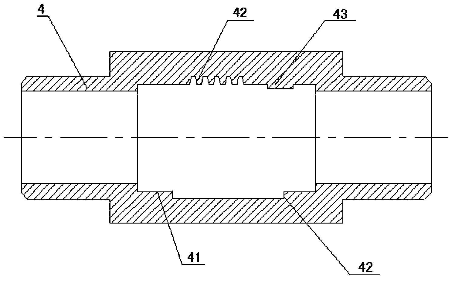
[0020] Cooperate see image 3 , Figure 4 , Figure 5 , Figure 6 , the rotor shaft 4 in the present invention is a metal hollow shaft, and the inner wall of the metal hollow shaft is provided with a ring groove 41 for inserting a plastic inner nut, and the ring groove wall is provided with a ring groove for preventing the plastic inner nut from radial rotation and axial movement. The concave-convex structure, the plastic inner nut 8 is embedded in the ring groove 41 and engages with the concave-convex structure.

[0021] Cooperate see image 3 , Figure 4 , the concavo-convex structure in one embodiment of the present invention includes at least...


PUM


Abstract

Provided is a stepping linear motor which comprises a stator, a rotor, a rotor shaft and a screw rod. The rotor shaft is internally provided with a plastic internal nut which is used for being connected with the screw rod in a transmission way. The rotor shaft is a metal hollow shaft. The internal wall of the metal hollow shaft is provided with a ring groove which is used for embedding the plastic internal nut. The wall of the ring groove is provided with a concave-convex structure which is used for preventing the plastic internal nut from radial rotation and axial movement. The plastic internal nut is embedded inside the ring groove and engaged with the concave-convex structure. According to the stepping linear motor, the rotor is relatively high in the service life, great in anti-rotating and stopping performance, high in injection molding nut intensity, relatively high in transmission efficiency, relatively low in heat radiation, great in injection molding degree, relatively high in transmission accuracy, etc.

Description

technical field [0001] The invention relates to a motor, in particular to a stepping linear motor. Background technique [0002] A stepping linear motor is a motor that converts rotary motion into linear motion through a screw. The stepping linear motor in the prior art is to make the inside of the rotating rotor shaft into an internal thread structure, and then insert the screw to realize the forward and backward movement of the screw when the motor rotates, such as figure 1 shown. However, threading directly inside the rotor shaft will shorten the life of the rotor. The improved method is to embed a plastic screw with self-lubricating function in the rotor shaft. How to connect the plastic and the rotor has become a problem that manufacturers need to solve. [0003] A method in the prior art is to drill a plurality of through holes around the center of the rotor shaft, and then directly inject plastic inner nuts in the rotor shaft through these through holes, such as ...

Claims


Application Information

Patent Timeline
Patent Type & Authority Applications(China)
IPC IPC(8): H02K7/06
CPCH02K7/06H02K41/03
Inventor 吴永松曾凯
Owner SHANGHAI MOONS ELECTRICAL APPLIANCE
Why Eureka
Try Eureka