Linear Motor

A linear motor and coil technology, applied in the direction of electrical components, electromechanical devices, electric components, etc., can solve the problems of limiting vertical thrust and horizontal thrust, limiting vertical magnetic density and horizontal magnetic density, etc.

Active Publication Date: 2017-02-22
SHANGHAI MICRO ELECTRONICS EQUIP (GRP) CO LTD
View PDF6 Cites 0 Cited by
  • Summary
  • Abstract
  • Description
  • Claims
  • Application Information

AI Technical Summary

Problems solved by technology

[0006] However, in the Halbach magnet arrays in the above two linear motors, since the direction of the plane flux density is inconsistent with the direction of the shape of the magnet array, the vertical magnetic flux and the horizontal magnetic flux will be limited, thereby limiting the vertical flux density and the horizontal flux density, and further limiting the Vertical thrust and horizontal thrust, ultimately limiting thrust in six degrees of freedom

Method used


Image

  • Linear Motor
  • Linear Motor
  • Linear Motor

Examples


Embodiment 1

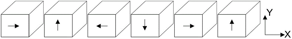
[0037] see Figure 4 and Figure 5 , Figure 4 A schematic structural view of the linear motor in Embodiment 1 of the present invention is given, wherein the magnet array is a cross-sectional view along the X axis, Figure 5 gives Figure 4 Schematic diagram of the three-dimensional structure of the magnet array. The linear motor provided in this embodiment includes a coil unit and a magnet unit. The magnet unit includes two groups of relatively parallel and symmetrical magnet arrays located on the yoke 100 . The coil unit is inserted between two sets of magnet arrays, the coil unit includes a coil 202 and a corresponding iron core 201 that can move relative to it, and the coil unit is close to but not in contact with the magnet array, that is, the coil unit is in contact with the magnet array. There are gaps between the magnet arrays. The magnet array is composed of first type magnets 111, second type magnets 112 and third type magnets 113 between them along the X axis ...

Embodiment 2

[0045] see Figure 8 , Figure 8 A schematic structural diagram of the linear motor according to Embodiment 2 of the present invention is given, wherein the magnet array is a cross-sectional view along the X axis. The difference between this embodiment and Embodiment 1 is that in the third type of magnet 123, the cross-sections along the XY plane of the first prism magnet 123a, the second prism magnet 123b and the third prism magnet 123c are right triangles respectively. , an isosceles trapezoid and a right triangle, wherein the magnetization direction of the first prism magnet 123a enters the second prism magnet 123b through its opposite surface with the second prism magnet 123b, and the magnetization direction of the second prism magnet 123b is parallel to the X axis And point to the first type of magnet 123a, the magnetization direction of the third prism magnet 123c is away from the second prism magnet 123b through its opposite surface with the second prism magnet 123b, o...

Embodiment 3

[0047] see Figure 9 , Figure 9 A schematic structural diagram of the linear motor according to Embodiment 3 of the present invention is given, wherein the magnet array is a cross-sectional view along the X-axis. The difference between this embodiment and Embodiment 1 is that the cross-sections along the XY plane of the first prism magnet 133a, the second prism magnet 133b and the third prism magnet 133c of the third type magnet 133 are right-angled trapezoid, isosceles triangle and right-angle respectively. trapezoidal, wherein the magnetization direction of the first prism magnet 133a enters the second prism magnet 133b through its opposite surface with the second prism magnet 133b, and the magnetization direction of the second prism magnet 133b is parallel to the X axis and points to the first type of magnet 133a, the magnetization direction of the third prism magnet 133c is away from the second prism magnet 133b through its opposite surface with the second prism magnet 1...


PUM


Abstract

The invention provides a linear motor which comprises a coil unit and a magnet unit. The magnet unit comprises two groups of symmetrical magnet arrays which are parallel relatively and are located on a magnet yoke, the magnet arrays are formed by a first-class magnet, a second-class magnet and a third-class magnet, the third-class magnet is arranged between the first-class magnet and the second-class magnet, the first-class magnet, the second-class magnet and the third-class magnet are periodically and alternatively distributed along an X axis in a Halbach magnet array mode, the first-class magnet and the second-class magnet are alternatively distributed along the X axis at an equal interval, and the magnetization direction of the first-class magnet and the magnetization direction of the second-class magnet are in the forward direction of a Y axis and the reverse direction of the Y axis. The third-class magnet is one prism magnet or comprises three prism magnets; when the third-class magnet is the prism magnet, the opposite surfaces of the adjacent magnets of different classes are both inclined planes; when the third-class magnet comprises the three prism magnets, the opposite surfaces of the adjacent different prism magnets are both inclined surface. Magnetic force lines formed in the linear motor are more continuous, the vertical magnetic flux and the horizontal magnetic flux in the magnet arrays can be improved, and therefore the pushing force in the corresponding direction can be improved.

Description

technical field [0001] The invention relates to a linear motor. Background technique [0002] With the advancement of lithography technology and the rapid development of the semiconductor industry, there are four basic performance indicators for lithography equipment: line width uniformity (CD, Critical Dimension Uniformity), focal depth (Focus), overlay (Overlay) and production Rate (Throughput). In order to improve the uniformity of line width, the workpiece table of lithography machine must improve the horizontal precision positioning ability; in order to improve the accuracy of focal depth error, the workpiece table must improve the vertical precision positioning ability; Improve its internal modality to improve dynamic positioning features. In addition, lithography equipment must increase throughput, so stages must move at high speeds and start and stop quickly. The high-speed, high-acceleration and high-precision positioning capabilities of lithography equipment are...

Claims


Application Information

Patent Timeline
Patent Type & Authority Patents(China)
IPC IPC(8): H02K41/03
Inventor 吴立伟杨晓燕陈庆生
Owner SHANGHAI MICRO ELECTRONICS EQUIP (GRP) CO LTD
Why Eureka
Try Eureka