Rotary clamping and cleaning device

A technology for cleaning devices and rotating components, which is applied in the directions of dry gas arrangement, cleaning methods and utensils, cleaning methods using liquids, etc. Reliable force, compact structure and space saving effect

Inactive Publication Date: 2014-02-19
YICHANG ENHANCE ULTRASONIC ELECTRIC
View PDF1 Cites 11 Cited by
  • Summary
  • Abstract
  • Description
  • Claims
  • Application Information

AI Technical Summary

Problems solved by technology

[0002] In the field of cleaning machines, for some shaft parts, especially those with uneven and porous surfaces, multi-station and cleaning of each hole are most commonly used in cleaning to achieve the required cleanliness, but this leads to equipment Large footprint and high manufacturing costs
[0003] Chinese patent 200910011043.9 discloses a crankshaft rotation cleaning and drying method and a special device. By controlling the rotation of the workpiece, the cleaning and drying mechanism is used to clean and dry the workpiece. The problem is that in order to achieve clamping and The rotary action adopts the sliding hanger to realize the axial displacement. With this mechanism, the overall structure of the equipment is not compact and takes up a lot of space. Since the hanger is a cantilever structure, the hanger has a parallelogram deformation when clamping the workpiece, and the force is not strong. Reliable, high power consumption
Especially the part where the hanger 33 is connected with the guide rod 4 has a complicated structure

Method used


Image

  • Rotary clamping and cleaning device
  • Rotary clamping and cleaning device
  • Rotary clamping and cleaning device

Examples


Embodiment Construction

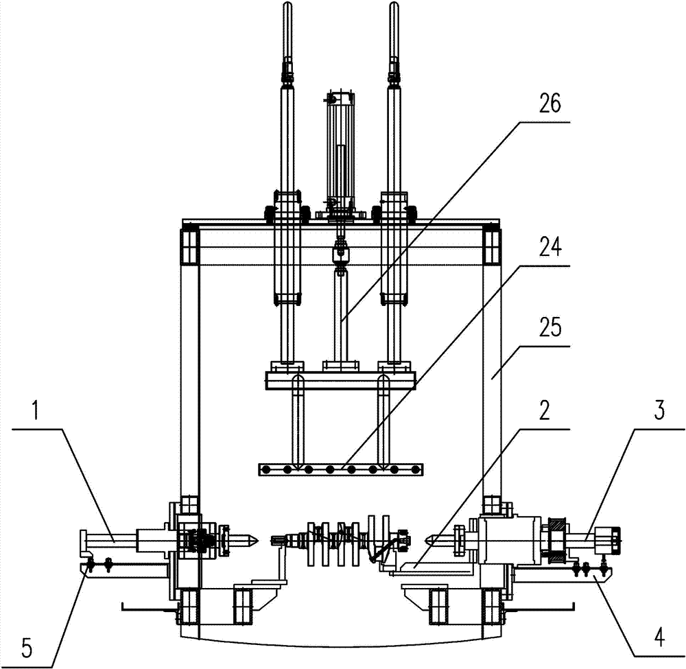
[0026] Such as figure 1 —— Figure 4 Among them, a rotary clamping cleaning device includes a frame 25, on which a jacking mechanism 1 and a rotary jacking mechanism 3 are arranged oppositely for clamping workpieces, and the frame is also provided with a cleaning and blowing mechanism. Cleaning and water blowing device 6 for dry workpieces;

[0027] The clamping mechanism 1 is provided with a mechanism for driving the axial displacement of the clamping top 12;

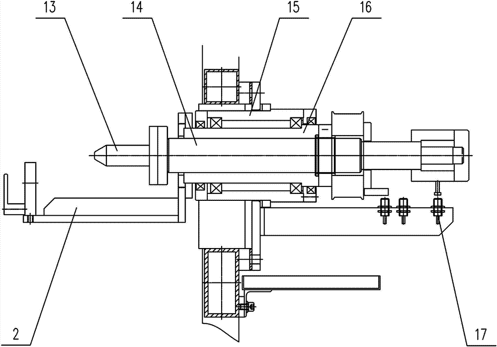
[0028] The rotary clamping mechanism 3 is provided with a mechanism for driving the axial displacement of the rotary clamping center 13 and driving the rotation of the workpiece.

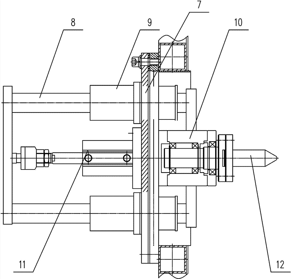
[0029] Such as figure 2 Among them, in the mechanism for driving the axial displacement of the tightening center 12, the tightening mounting plate 7 is connected to the frame 25 in a floating manner, and the tightening center 12 is freely rotatably installed on the tightening rotating assembly 10; the tightening center 12 The clamping c...


PUM


Abstract

A rotary clamping and cleaning device comprises a rack. A tightly-jacking mechanism and a rotary tightly-jacking mechanism which are arranged oppositely and used for clamping a workpiece are arranged on the rack, a cleaning and water-blowing device used for cleaning and blow-drying the workpiece is further arranged on the rack, a mechanism driving a tightly-jacking tip to axially displace is arranged in the tightly-jacking mechanism, and a mechanism driving a rotary tightly-jacking tip to axially displace and driving the workpiece to rotate is arranged in the rotary tightly-jacking mechanism. By adopting the above structure, cleaning, blow-drying and water-pouring after cleaning of surfaces and holes, high in cleanliness requirements, of several shaft-class parts can be realized. The rotary clamping and cleaning device has the advantages that at a same workstation, cleaning and blow-drying of the surface and multiple holes of the workpiece can be realized by rotating and positioning the workpiece from different angles. The rotary clamping and cleaning device is compact in integral structure, reliable in stress, simple, flexible and space saving.

Description

technical field [0001] The invention relates to a clamping mechanism for cleaning shaft parts in cleaning equipment, in particular to a rotary clamping cleaning device for cleaning and drying the surface and multiple holes of the shaft parts. Background technique [0002] In the field of cleaning machines, for some shaft parts, especially those with uneven and porous surfaces, multi-station and cleaning of each hole are most commonly used in cleaning to achieve the required cleanliness, but this leads to equipment The floor area is large, and the manufacturing cost is high. [0003] Chinese patent 200910011043.9 discloses a crankshaft rotation cleaning and drying method and a special device. By controlling the rotation of the workpiece, the cleaning and drying mechanism is used to clean and dry the workpiece. The problem is that in order to achieve clamping and The rotary action adopts the sliding hanger to realize the axial displacement. With this mechanism, the overall st...

Claims


Application Information

Patent Timeline
Patent Type & Authority Applications(China)
IPC IPC(8): B08B3/02B08B13/00F26B5/00
CPCB08B3/02B08B13/00F26B21/00
Inventor 梁丽萍覃芝松高续业
Owner YICHANG ENHANCE ULTRASONIC ELECTRIC
Why Eureka
Try Eureka