Large-tonnage movable trolley with convertible load distribution

A large-tonnage, moving technology, applied in the transportation of passenger cars, transportation and packaging, railway car body parts, etc., can solve the problems of high purchase, use and maintenance costs of handling machines, long equipment processing cycle, and short service life. , to achieve uniform load distribution, reduce production costs and improve service life.

Active Publication Date: 2014-02-19
WUHAN BRIDGE HEAVY INDS GROUP
View PDF6 Cites 3 Cited by
  • Summary
  • Abstract
  • Description
  • Claims
  • Application Information

AI Technical Summary

Problems solved by technology

In the hanging beam scheme, the span of the moving track of the moving machine is required to be large enough to cover the manufacturing site of the prefabricated parts. The purchase, use and maintenance costs of the moving machine are high, the processing cycle of the equipment is long, and its operation is complicated
[0004] The large-scale bridge prefabrication site generally adopts the transfer trolley scheme. The existing transfer trolley is a single-layer beam composed of two distribution beams. Two points of force, such as attached figure 2 As shown, the two points J and K on the track 3 in contact with the trolley are stressed. Therefore, there are high requirements for the running track of the transfer trolley. Concrete piles must be laid on the running track to prevent the track from sinking, and laying on the surface Sliding track, high cost and relatively short service life

Method used


Image

  • Large-tonnage movable trolley with convertible load distribution
  • Large-tonnage movable trolley with convertible load distribution
  • Large-tonnage movable trolley with convertible load distribution

Examples


Embodiment Construction

[0017] Now further illustrate how the present invention is implemented in conjunction with accompanying drawings:

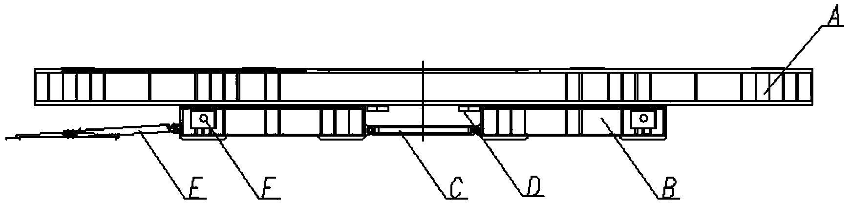
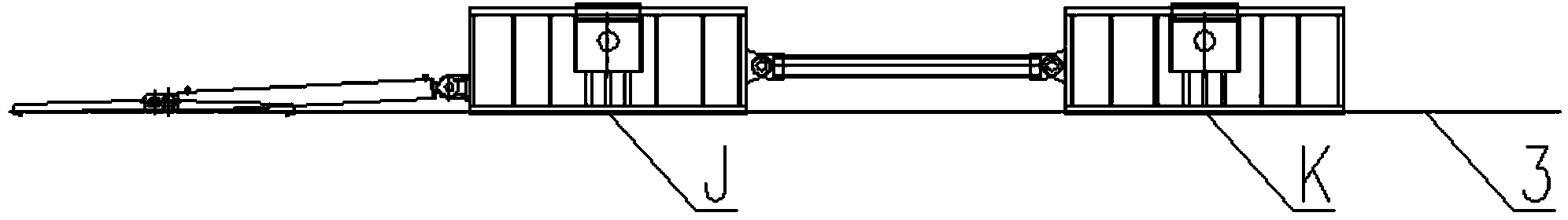
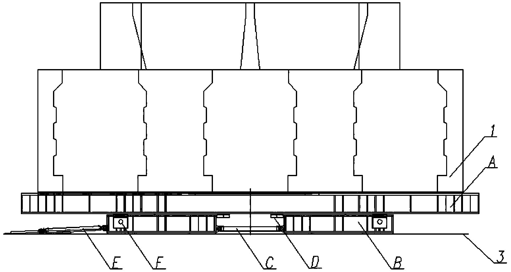
[0018] The present invention is a large tonnage displacement trolley capable of load conversion and distribution, which is composed of two sets of unilateral transport trolleys, a PLC control system and a hydraulic pump station. The side shift trolley is composed of the upper beam, the lower beam, the support plate, the jacking cylinder and the traveling cylinder. The traveling cylinder E and the jacking cylinder F are respectively connected to the corresponding hydraulic pump stations, and the traveling cylinder E is connected to the transfer trolley. ;The lower beam is composed of two identical lower distribution beams B, the two lower distribution beams B are horizontally spaced apart, their inner ends are connected by connecting rods C, and their outer ends are respectively equipped with jacking cylinders F, the upper beam A, two The center lines of the lower...


PUM


Abstract

The invention relates to a large-tonnage movable trolley with convertible load distribution, and belongs to the field of heavy movable transportation machines. According to the large-tonnage movable trolley, two single-side movable trolley sets are arranged on the two sides; each single-side movable trolley set is composed of upper layer beams, lower layer beams, supporting base plates, jacking oil cylinders and a walking oil cylinder; two lower layer distribution beams of each lower layer beam are connected through a connecting rod, the outer side ends of the lower layer beams are provided with the jacking oil cylinders respectively, the upper layer beams are symmetrically arranged on the two lower layer distribution beams, and the two supporting base plates are placed between the two lower layer distribution beams and can slide along upper layer distribution beams. The upper layer beams are jacked through the oil cylinders first, the supporting base plates are pulled to the central positions of the lower layer distribution beams, after the oil cylinders are unloaded, upper layer beam loads are evenly distributed to the two ends of the two lower layer beams through the supporting base plates so that four load supporting points can be formed, and therefore the single-side track plane of a single-side movable trolley is changed from two-point stress into four-point stress. By the adoption of the structure, the loads can be evenly distributed, the difficult problem of an existing track is solved, the manufacturing cost of the track is greatly lowered, and the efficiency is improved.

Description

technical field [0001] The invention relates to a large tonnage displacement trolley with convertible load distribution, which belongs to the field of heavy-duty mobile transportation machinery, and in particular relates to a bridge prefabricated part mobile transportation machinery. Background technique [0002] In bridge erection, the manufacture and transportation of prefabricated concrete girders and prefabricated piers are important links. The prefabricated pier is a towering structure with heavy weight and high center of gravity, which requires uniform load distribution and gentle movement during transportation. , transportation is extremely difficult. Prefabricated parts are generally prefabricated in the beam yard, moved to the dock or other installation locations by equipment, and installed by special equipment. [0003] In the transfer construction of prefabricated bridge piers in beam yards, two basic methods are usually adopted. One is to use transfer trolleys t...

Claims


Application Information

Patent Timeline
Patent Type & Authority Applications(China)
IPC IPC(8): B61D15/00
Inventor 任继新谢继伟容建华李畅哲周江明张征明朱武珍刘炎冷志坚周红安方晶陶海洋
Owner WUHAN BRIDGE HEAVY INDS GROUP
Why Eureka
Try Eureka