
High-temperature high-pressure large-drift-diameter hydraulic sleeve packer

A high-temperature, high-pressure, large-diameter technology, applied in sealing/packing, wellbore/well components, earthwork drilling and production, etc., can solve problems such as unstable performance, low temperature resistance, and high price of packers

Inactive Publication Date: 2014-02-19
CHINA PETROLEUM & CHEM CORP
View PDF8 Cites 3 Cited by
  • Summary
  • Abstract
  • Description
  • Claims
  • Application Information

AI Technical Summary

Problems solved by technology

[0003] The purpose of the present invention is to aim at the existing domestic casing packer bearing pressure and low temperature resistance, the imported high temperature and high pressure casing packer is expensive, and the domestic SHR-HP packer has small diameter, unstable performance and effective sealing The shortage of short time provides a high-temperature and high-pressure large-bore casing packer suitable for high-temperature, high-pressure gradient and high-pressure wells

Method used


Image

  • High-temperature high-pressure large-drift-diameter hydraulic sleeve packer
  • High-temperature high-pressure large-drift-diameter hydraulic sleeve packer
  • High-temperature high-pressure large-drift-diameter hydraulic sleeve packer

Examples


Embodiment Construction

[0011] The present invention is not limited by the following examples, and specific implementation methods can be determined according to the technical solutions of the present invention and actual conditions.

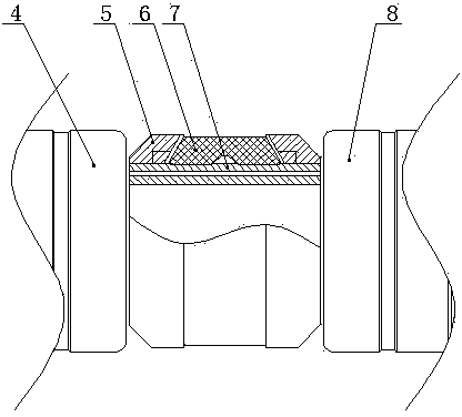
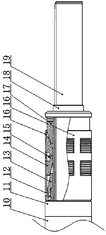
[0012] Example: such as figure 1 As shown in —3, the high-temperature, high-pressure and large-diameter casing hydraulic packer includes an inner central pipe 19, a combined sealing rubber cylinder piece sleeved on the inner central pipe 19, a setting piston piece, a locking piece 11, and a slip group 14 and 18 parts of the outer central tube. An upper joint 1 is screwed to the front end of the inner central tube 19, and the release sleeve 2 is connected outside the upper joint 1 through a release nut and a shear pin, and the balance joint 3 is screwed under the release sleeve 2. The combined sealing rubber cylinder part is sleeved on the core sleeve 7, the core sleeve 7 is sleeved outside the inner center pipe 19, and the upper end of the core sleeve 7 is screwed to ...


PUM


Abstract

The invention relates to a high-temperature high-pressure large-drift-diameter hydraulic sleeve packer which comprises an inner central tube, a combined sealing rubber cylinder part, a setting piston part, a locking part, a slip set and an outer central tube, wherein the combined sealing rubber cylinder part, the setting piston part, the locking part, the slip set and the outer central tube are connected to the inner central tube in a sleeved mode. The front end of the inner central tube is connected with an upper connector in a screwed mode, a release sleeve is connected to the outer side of the upper connector, and the lower portion of the release sleeve is connected with a balancing connector in a screwed mode. A core sleeve is sleeved with the combined sealing rubber cylinder part, the inner central tube is sleeved with the core sleeve, and the upper end of the core sleeve is connected with the balancing connector in a screwed mode. The combined sealing rubber cylinder part comprises a rubber cylinder and a metal net, an upper guide ring and a lower guide ring butt against the upper side of the combined sealing rubber cylinder part and the lower side of the combined sealing rubber cylinder part, the upper guide ring is connected with the balancing connector in a screwed mode, the lower guide ring is connected with an oil drainage sleeve in a screwed mode, and the lower portion of the oil drainage sleeve is sequentially connected with a cylinder sleeve, the locking part and the slip set in a screwed mode. The setting piston part is arranged in the cylinder sleeve, the slip set is fixed into a slip sleeve through an upper cone and a lower cone, and the outer central tube is sleeved with the slip set in a wrapping mode. The high-temperature high-pressure large-drift-diameter hydraulic sleeve packer is high in pressure bearing capacity, high in temperature resistance, large in drift diameter, high in overall stability and long in effective separation time.

Description

technical field [0001] The invention relates to a high-temperature, high-pressure and large-diameter casing hydraulic packer used in the process of reservoir reconstruction measures and production of oil and gas wells. Background technique [0002] The function of the casing packer is to separate the oil casing at a certain depth downhole and protect the casing and the wellhead when the high-pressure gradient well undergoes reservoir stimulation such as acid fracturing and high-pressure well production. With the continuous development of exploration and development, oil and gas wells are getting deeper and deeper, and the pressure gradient of ground breaking is getting higher and higher, so the requirements for pressure bearing and temperature resistance of packers are getting higher and higher. At present, the commonly used domestic casing packers have a maximum pressure difference of 52MPa and a maximum temperature resistance of 150°C. The high-temperature and high-pressur...

Claims


Application Information

Patent Timeline
IPC IPC(8): E21B33/126
Inventor 张梦华李海军刘练王鹏辉王博伟谢进邹伟周生福张佳
Owner CHINA PETROLEUM & CHEM CORP
Learn More