Temperature control device and control method for pumping hydraulic system and engineering machinery

A technology of a temperature control device and a temperature control method, which is applied to fluid pressure actuation devices, fluid pressure actuation system components, mechanical equipment, etc., and can solve problems such as large output displacement and power waste

Active Publication Date: 2014-02-19
ZOOMLION HEAVY IND CO LTD
View PDF6 Cites 5 Cited by
  • Summary
  • Abstract
  • Description
  • Claims
  • Application Information

AI Technical Summary

Problems solved by technology

[0003] 1) When the temperature of the hydraulic system is low, the output oil of the main pump returns to the oil tank through the middle position of the reversing valve, and there is a pressure loss when the oil flows through the pipeline and components. At this time, if the main pump still has a large output displacement, at a certain waste of power

Method used


Image

  • Temperature control device and control method for pumping hydraulic system and engineering machinery
  • Temperature control device and control method for pumping hydraulic system and engineering machinery
  • Temperature control device and control method for pumping hydraulic system and engineering machinery

Examples


Embodiment Construction

[0024] Hereinafter, the present invention will be described in detail with reference to the drawings and examples. It should be noted that, in the case of no conflict, the embodiments in the present application and the features in the embodiments can be combined with each other.

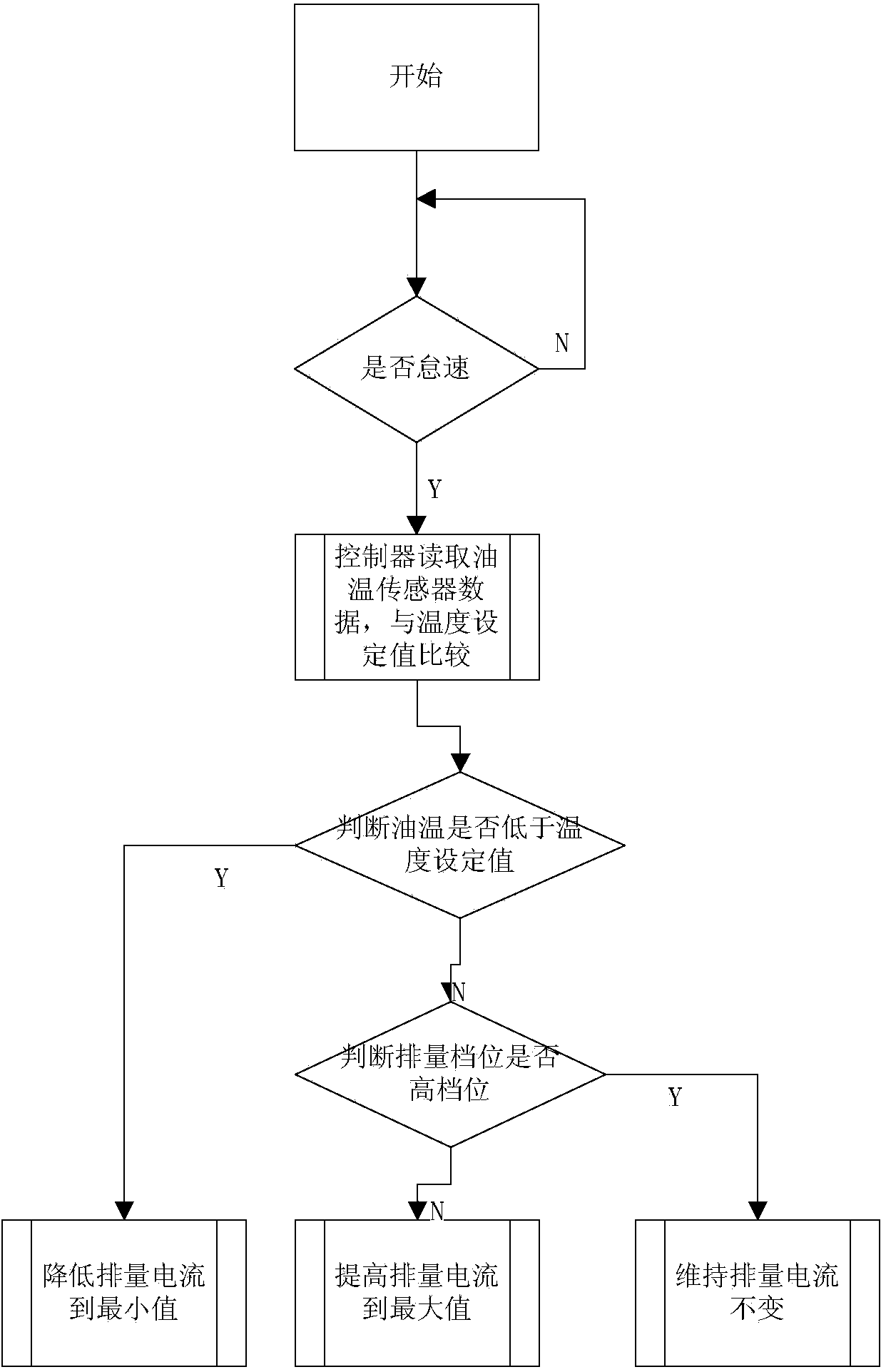
[0025] In this embodiment, the displacement gears of the hydraulic pump are divided into high and low gears. For example, if the displacement gears are divided into 5 gears, the 1st and 2nd gears are low gears, and the 3rd, 4th, and 5th gears are high gears. , if the displacement gears are divided into 4 gears, then the 1st and 2nd gears are low gears, and the 3rd and 4th gears are high gears. The division of gears here is based on the general understanding of those skilled in the art. The situation is determined by the operator himself.

[0026] like figure 1 As shown, according to an embodiment of the present invention, the temperature control method of the pumping hydraulic system includes: dete...


PUM


Abstract

The invention provides a temperature control device and control method for a pumping hydraulic system and engineering machinery. The temperature control method form the pumping hydraulic system comprises the steps of determining whether the pumping hydraulic system is in an idling work state, detecting the temperature of hydraulic oil of the pumping hydraulic system when the pumping hydraulic system is in the idling work state, and adjusting the displacement of a hydraulic pump according to the detected temperature of the hydraulic oil. The temperature control method for the pumping hydraulic system effectively reduces system power waste and meanwhile guarantees the work temperature of the hydraulic system.

Description

technical field [0001] The invention relates to the field of pumping machinery, in particular to a temperature control device and control method for a pumping hydraulic system, and construction machinery. Background technique [0002] Due to the limitation of the overall structure of the concrete pump, the design of the fuel tank is usually small, and the working condition of the concrete pump, especially the diesel engine pump is harsh, and the heat generation of the hydraulic system is relatively high. In the prior art, when the hydraulic system is in the idling state, the proportional electromagnet that controls the displacement output of the main pump is energized, and the current is the same as that during normal pumping. This control method has the following two defects: [0003] 1) When the temperature of the hydraulic system is low, the output oil of the main pump returns to the oil tank through the middle position of the reversing valve, and there is a pressure loss...

Claims


Application Information

Patent Timeline
Patent Type & Authority Applications(China)
IPC IPC(8): F15B21/04
Inventor 段寄伟李剑刘如意
Owner ZOOMLION HEAVY IND CO LTD
Why Eureka
Try Eureka