Eureka AIR delivers breakthrough ideas for toughest innovation challenges, trusted by R&D personnel around the world.

Transmission for a motor vehicle

一种变速器、汽车的技术,应用在车辆变速箱、车辆部件、带有齿的元件等方向,能够解决高费用等问题,达到控制技术简化、成本低、结构的简化的效果

Inactive Publication Date: 2014-02-19
ZF FRIEDRICHSHAFEN AG
View PDF8 Cites 1 Cited by
  • Summary
  • Abstract
  • Description
  • Claims
  • Application Information

AI Technical Summary

Problems solved by technology

This requires a rather high outlay for the actuating device and its control

Method used


Image

  • Transmission for a motor vehicle
  • Transmission for a motor vehicle
  • Transmission for a motor vehicle

Examples


Embodiment Construction

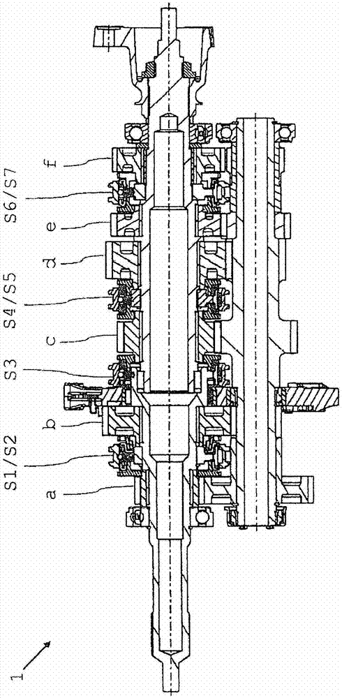
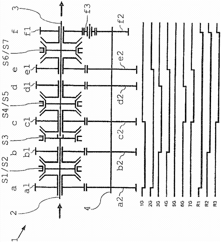
[0039] a press figure 1 The transmission for automobiles has six gear set planes a, b, c, d, e, f and seven gear clutches S1, S2, S3, S4, S5, S6, S7. Depend on figure 2 The transmission structure can be easily seen.

[0040] The transmission 1 is designed as an intermediate shaft transmission comprising a drive-side input shaft 2 , a driven-side output shaft 3 arranged coaxially behind the input shaft, and an intermediate shaft 4 arranged axially parallel to these transmission shafts 2 , 3 .

[0041] The six gear set planes a to f are respectively formed as spur gear pairs a1 / a2, b1 / b2, c1 / c2, d1 / d2, e1 / e2, f1 / f2 in meshing toothing, with the last gear set plane f A steering reversal gear f3 with a rotatable bearing is added in order to enable the respective reverse gears. The spur gear pairs a1 / a2, b1 / b2, c1 / c2, d1 / d2, e1 / e2, f1 / f2 respectively have: idler gears a1, b1, c1, d1, e1, f1, which are rotatably supported on On the input shaft 2 or the output shaft 3 and can be...


PUM


Abstract

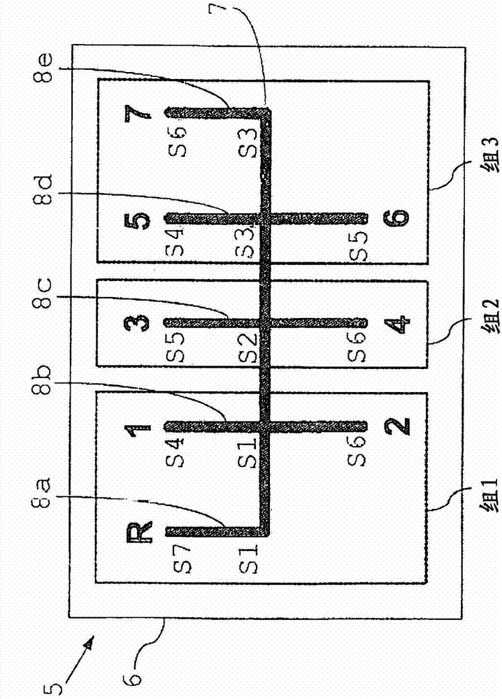
The invention relates to a transmission (1) for a motor vehicle. Gear clutches (S1, S2, S3, S4, S5, S6, S7) are divided into a selection group and a shifting group. The selection group gear clutches (S1, S2, S3) can be actuated exclusively by moving a shift lever in the selection gate (7) so as to couple an input shaft (2) and a counter shaft (4). The shifting group gear clutches (S4, S5, S6, S7) can be actuated exclusively by moving a shift lever in the shifting gates (8a, 8b, 8c, 8d, 8e) so as to couple an output shaft (3) and the counter shaft (4), and the gear clutch (S1, S2, S3) respectively engaged in the shifting gates (8b, 8c, 8d) having the two opposite gears is a selection group gear clutch.

Description

technical field [0001] The invention relates to a motor vehicle transmission according to the preamble of claim 1 . Background technique [0002] Transmissions have been used for a long time in the powertrains of motor vehicles, which are constructed in the manner of a countershaft and which can be actuated by manual shifting. In conventional countershaft transmissions, idler gears and fixed gears are provided in multiple gear set planes, which are in tooth meshing in pairs. In particular, the switching of the transmission gear is realized by opening the first gear clutch of the connected gear and closing the gear clutch of a target gear, and the non-relatively rotatable connection between an idler gear and a transmission wheel is disengaged at this time, involving The idler gear is rotatably supported on the transmission shaft, creating another non-rotatable connection between an idler gear and a transmission shaft. The rotating components of the target gear to be engaged...

Claims


Application Information

Patent Timeline
Patent Type & Authority Applications(China)
IPC IPC(8): F16H3/08F16H59/02
CPCF16H2200/0091F16H3/0915F16H2200/0056F16H3/08Y10T74/19219
Inventor C·尼古拉齐格
Owner ZF FRIEDRICHSHAFEN AG
Why Eureka
Eureka Blog
Learn More