Analog photoelectric isolation conversion circuit based on time ratio pwm modulation

A PWM circuit and time ratio technology, applied in the direction of logic circuits using optoelectronic equipment, logic circuits using specific components, etc., can solve the problems of high requirements on linearity of devices, easy to be interfered, and difficult to adjust, etc. Interference ability, expansion of use range, effect of suppressing noise signals

Inactive Publication Date: 2016-09-07
TIANJIN UNIV
View PDF3 Cites 0 Cited by
  • Summary
  • Abstract
  • Description
  • Claims
  • Application Information

AI Technical Summary

Problems solved by technology

Although the volume and weight of the linear optocoupler is small, it has high requirements on the linearity of the device for signals that vary in a large range, and it is not easy to adjust, and its transmission is still an analog signal, which is susceptible to interference

Method used


Image

  • Analog photoelectric isolation conversion circuit based on time ratio pwm modulation
  • Analog photoelectric isolation conversion circuit based on time ratio pwm modulation
  • Analog photoelectric isolation conversion circuit based on time ratio pwm modulation

Examples


Embodiment Construction

[0027] The technical solutions of the present invention will be further described below in conjunction with specific embodiments.

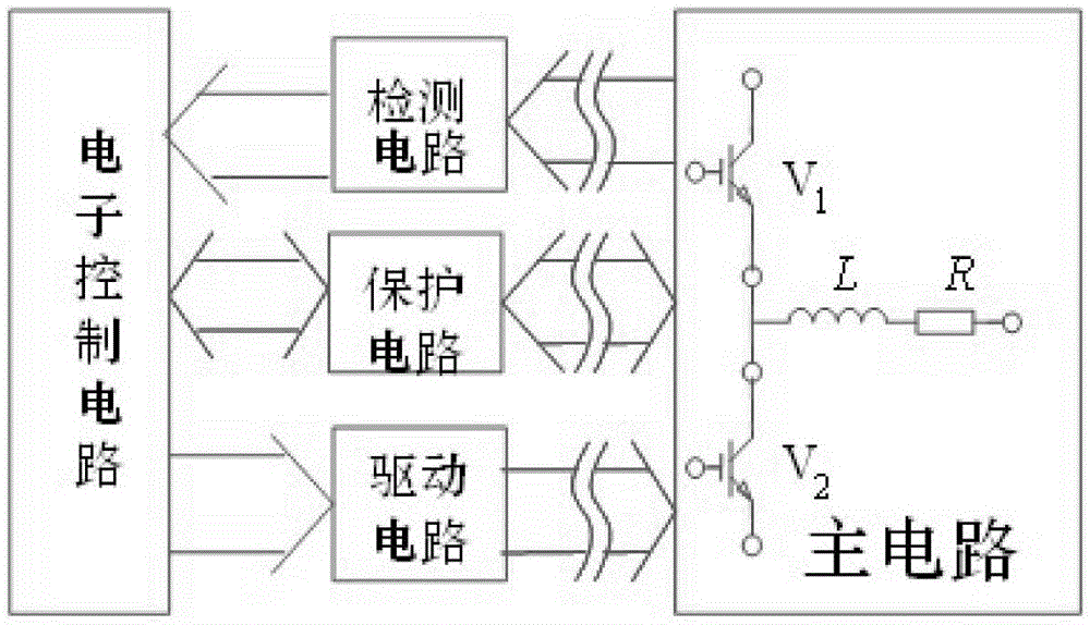
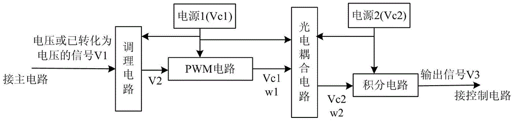
[0028] as attached figure 2 The circuit structure diagram shown is divided into two parts by the photoelectric coupling circuit. The left part is mainly composed of a conditioning circuit and a PWM circuit, which is directly connected to the main circuit and powered by power supply 1; the right part is mainly an integrating circuit. It is directly connected to the control circuit and powered by power supply 2; power supply 1 and power supply 2 are electrically independent from each other, and the two parts of the circuit transmit signals through the photoelectric coupling circuit to achieve electrical isolation.

[0029] The above circuit receives the signal V1 from the main circuit (for example: the voltage signal stepped down by the voltage dividing resistor, the current signal transformed by the shunt), and is processed by the conditioning cir...


PUM


Abstract

The invention discloses an analog photoelectric isolation conversion circuit based on time ratio PWM modulation, which is divided into two parts with the photoelectric coupling circuit as the boundary. One part is mainly composed of a conditioning circuit and a PWM circuit, and is directly connected with the main circuit; , directly connected with the control circuit; the first and second power supplies are electrically independent of each other, and the two parts of the circuit transmit signals through the photoelectric coupling circuit to achieve electrical isolation. The technical scheme of the present invention first converts the analog signal into a pulse signal, acts on the integrating circuit through photoelectric coupling, and then converts it into an analog signal, which not only realizes the electrical isolation of the main circuit and the control circuit, but also utilizes the characteristics of PWM pulse and photoelectric coupling. The anti-interference ability of the transmission signal is improved; further, the characteristics of PWM pulse transmission can be used to carry out long-distance signal transmission by enhancing the intensity of the PWM pulse, thereby expanding the use range of the circuit.

Description

technical field [0001] The invention belongs to material processing technology, and more specifically relates to a method and a measurement circuit for electrical isolation and simulated noise interference in the electrical parameter detection process of electrical equipment. Background technique [0002] In many electrical equipment, the circuit is often composed of a main circuit (power circuit) and a control circuit (electronic circuit). The main circuit outputs energy to do work, and the control circuit obtains signals related to the main circuit (such as current, voltage, temperature, speed, etc.) to Control the energy output of the main circuit and display or record relevant parameters. The signals related to the main circuit are generally converted into voltage signals to facilitate the processing of the control circuit. It may be necessary to set up electrical isolation measures and anti-corrosion measures between the main circuit and the control circuit due to facto...

Claims


Application Information

Patent Timeline
Patent Type & Authority Patents(China)
IPC IPC(8): H03K19/14
Inventor 杨立军田丽峰刘桐王会超焦娇杜笑李桓
Owner TIANJIN UNIV
Why Eureka
Try Eureka