Continuously variable transmission

A technology of continuously variable transmission and transmission, which is applied in transmission devices, friction transmission devices, belts/chains/gears, etc. It can solve the problems of peripheral speed difference, power transmission efficiency reduction, loss, etc., and achieve friction loss reduction and loss energy change. Small, spin loss reduction effect

Inactive Publication Date: 2014-02-19
TOYOTA JIDOSHA KK
View PDF7 Cites 5 Cited by
  • Summary
  • Abstract
  • Description
  • Claims
  • Application Information

AI Technical Summary

Problems solved by technology

[0009] However, as a result, in the existing continuously variable transmissions that can be cited so far, regardless of the deflection angle of the planetary balls, the bearings (thrust bearings, angular contact bearings) arranged between the sun roller and the transmission shaft There will be a large peripheral speed difference between the outer ring and the inner ring, resulting in a large loss caused by the product of the peripheral speed difference and thrust
That is, in the conventional continuously variable transmission, along with the rotation of the rotating element interposed between the transmission shaft and the rolling member (the same applies to the sun roller of the above-mentioned patent document 1 and the disc of the above-mentioned patent document 3), A difference in peripheral speed occurs between the inner and outer rings of a bearing with a rotating element (the peripheral speed of the inner ring is substantially zero)
Since this difference in peripheral speed occurs regardless of the deflection angle of the rolling elements, in this conventional continuously variable transmission, the loss energy at the bearing becomes large regardless of the transmission ratio (deflection angle of the planetary balls), resulting in dynamic Reduced transfer efficiency

Method used


Image

  • Continuously variable transmission
  • Continuously variable transmission
  • Continuously variable transmission

Examples


Embodiment 1

[0030] based on Figure 1 to Figure 6 Embodiment 1 of the continuously variable transmission according to the present invention will be described.

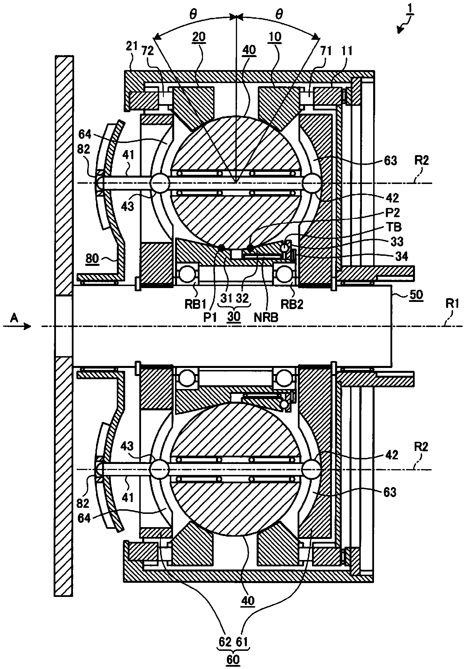
[0031] First, use figure 1 An example of the continuously variable transmission of this embodiment will be described. figure 1 The numeral 1 in the . represents the continuously variable transmission of this embodiment.

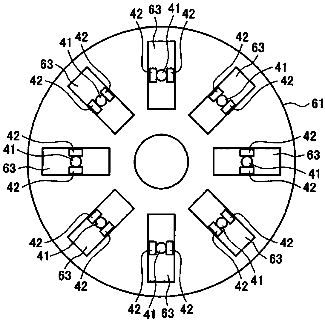
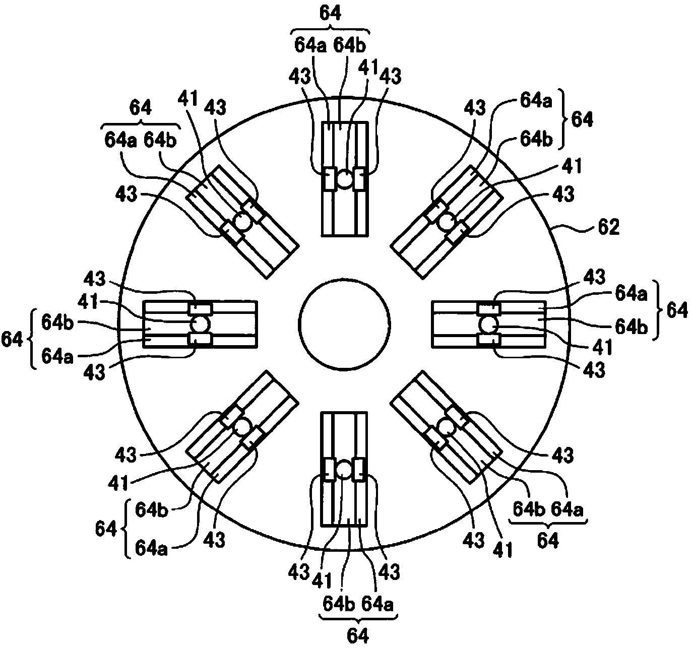
[0032] The continuously variable transmission mechanism constituting the main part of the continuously variable transmission 1 is a so-called traction planetary gear mechanism, and includes first to third rotation elements having a common first rotation center axis R1 and being rotatable relative to each other. 10, 20, 30; a plurality of them are radially arranged around the first rotation center axis R1, and each has another second rotation center axis parallel to the first rotation center axis R1 at a reference position described later. The rolling member 40 of R2; the shaft 50 serving as the transmission sh...

Embodiment 2

[0071] Second, based on Figure 7 to Figure 12 Embodiment 2 of the continuously variable transmission according to the present invention will be described.

[0072] In the continuously variable transmission 1 and the continuously variable transmission 2 of the above-mentioned embodiment 1, in order to reduce the friction loss caused by the rotation difference between the thrust bearing TB and the angular contact bearing AB during deflection (when the transmission ratio γ≠1), it is preferable Lubricating oil is supplied to the thrust bearing TB and the angular contact bearing AB. In this second embodiment, a structure for supplying lubricating oil will be described.

[0073] Figure 7 The reference numeral 3 in represents the continuously variable transmission of this embodiment. This continuously variable transmission 3 is obtained by replacing the sun roller 30 with the sun roller 230 and replacing the shaft 50 with the shaft 150 in the continuously variable transmission 1...


PUM


Abstract

The present invention comprises a plurality of planet balls (40) sandwiched between first and second rotating members (10, 20) on a shaft (50); an iris plate (80) and a worm gear (81) spinning each of the planet balls (40) at a slope; a sun roller (30) comprising a first sun roller (31) which includes a first cylindrical portion (31a) that has a first contact point (P1) with the planet ball (40) and a second cylindrical portion (31b) that has a smaller outer diameter than the first cylindrical portion (31a) to be capable of relative rotation with the shaft (50), the sun roller (30) also comprising a second sun roller (32) which includes a second contact point (P2) with the planet ball (40) to be capable of relative rotation with the first sun roller (31) on an outer circumferential surface of the second cylindrical portion (31b); and a thrust bearing (TB) disposed between the first sun roller (31) and the second sun roller (32) to receive a thrust load in a shaft line direction transmitted from the planet ball (40) to the first sun roller (31) and the second sun roller (32).

Description

technical field [0001] The present invention relates to a continuously variable transmission that includes a plurality of rotating elements having a common rotating shaft and a plurality of rolling members arranged radially with respect to the rotating shaft, and by using two of the rotating elements Each rolling member sandwiched by the rotating element deflects to continuously change the gear ratio between input and output. Background technique [0002] Conventionally, a so-called traction planetary gear mechanism has been known as such a continuously variable transmission. Such a traction planetary gear mechanism includes: a transmission shaft serving as a center of rotation; a plurality of rotating elements that are relatively rotatable with the center axis of the transmission shaft as a first rotation center axis; The second rotation center shaft, and a plurality of rolling members are arranged radially around the first rotation center shaft; the support shaft that mak...

Claims


Application Information

Patent Timeline
Patent Type & Authority Applications(China)
IPC IPC(8): F16H15/52
CPCF16H15/28F16H15/52F16H57/0427F16H57/043F16H57/0487F16H15/503
Inventor 小川裕之友松大辅村上新椎名贵弘荒津有希
Owner TOYOTA JIDOSHA KK
Why Eureka
Try Eureka