Stamping die

A technology for stamping molds and mold shells, applied in the field of molds, which can solve problems such as smashing hands, increasing the stroke of punches, and time-consuming, so as to improve work efficiency, speed up stamping speed, and eliminate potential safety hazards.

Inactive Publication Date: 2014-02-26
XINGHUA TIEXIN ELECTRONICS ENG
View PDF6 Cites 5 Cited by
  • Summary
  • Abstract
  • Description
  • Claims
  • Application Information

AI Technical Summary

Problems solved by technology

[0003] The stamping dies of the prior art have the following defects: each time a screw is punched, five steps of mold opening, loading, stamping mold clamping, mold opening, and demoulding need to be carried out separately, and as many screws as needed to be stamped need to be repeated as many times as necessary. The speed is slow and the efficiency is low, and continuous stamping and forming cannot be performed; secondly, because the round bar is placed between the upper mold and the lower mold when discharging, in this way, if the mold opening range is too small before

Method used


Image

  • Stamping die
  • Stamping die
  • Stamping die

Examples


Embodiment Construction

[0017] The present invention will be further described below in conjunction with the accompanying drawings and specific embodiments.

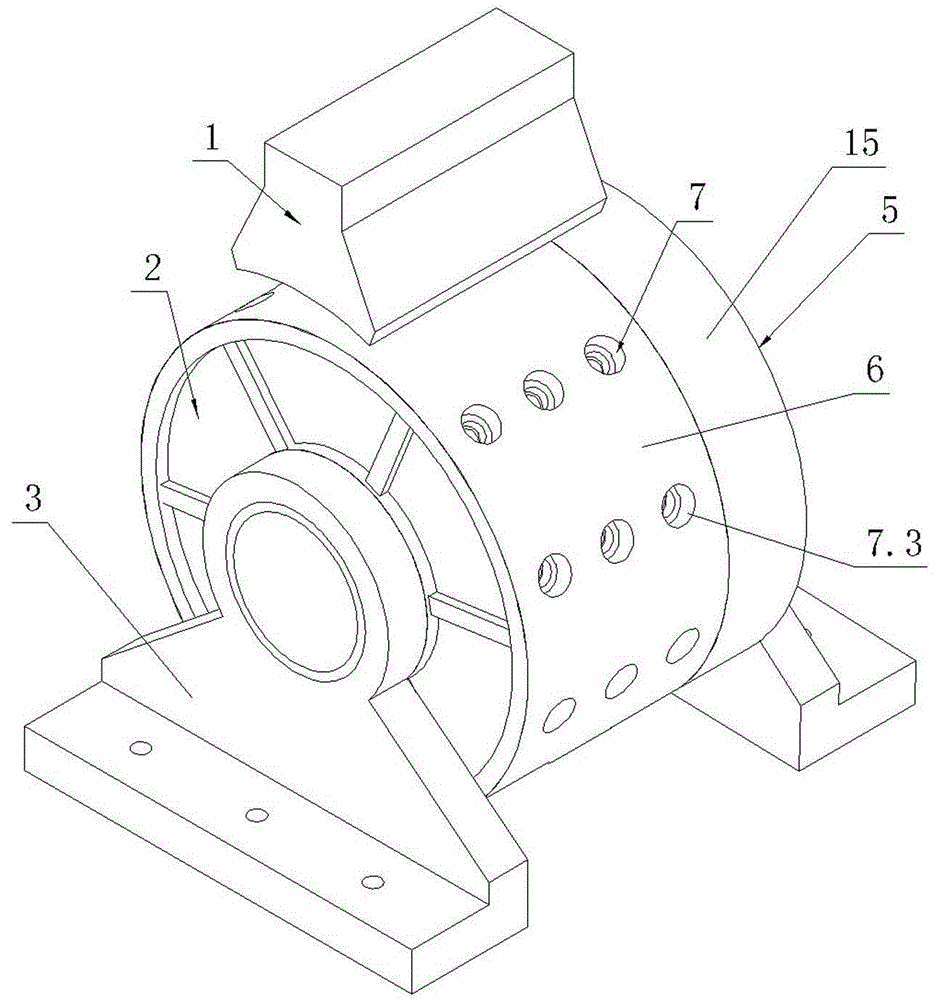
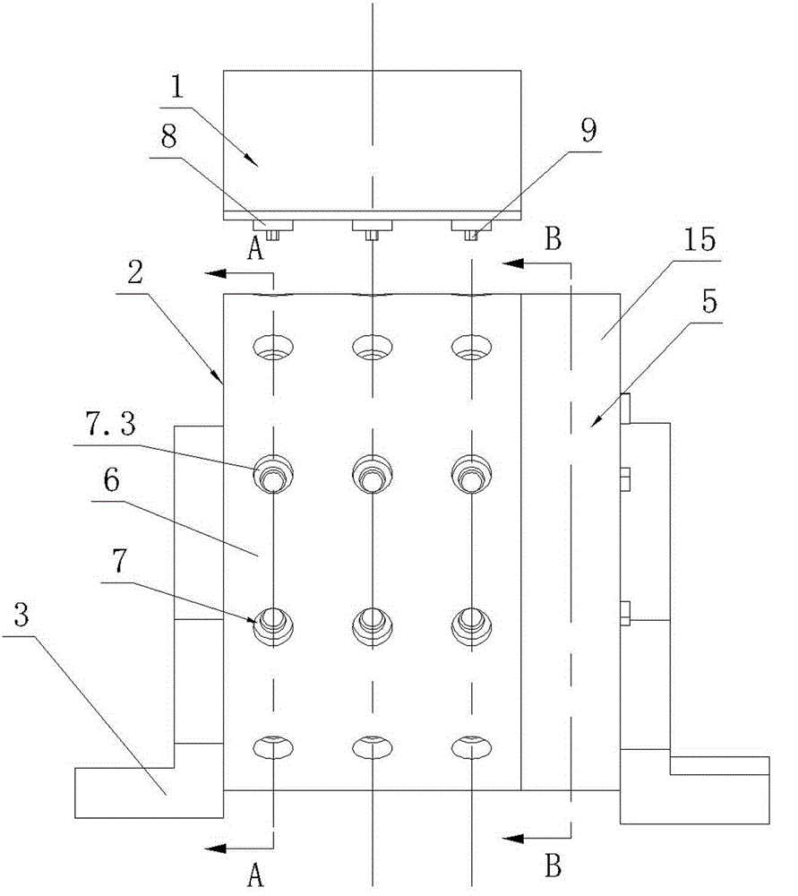
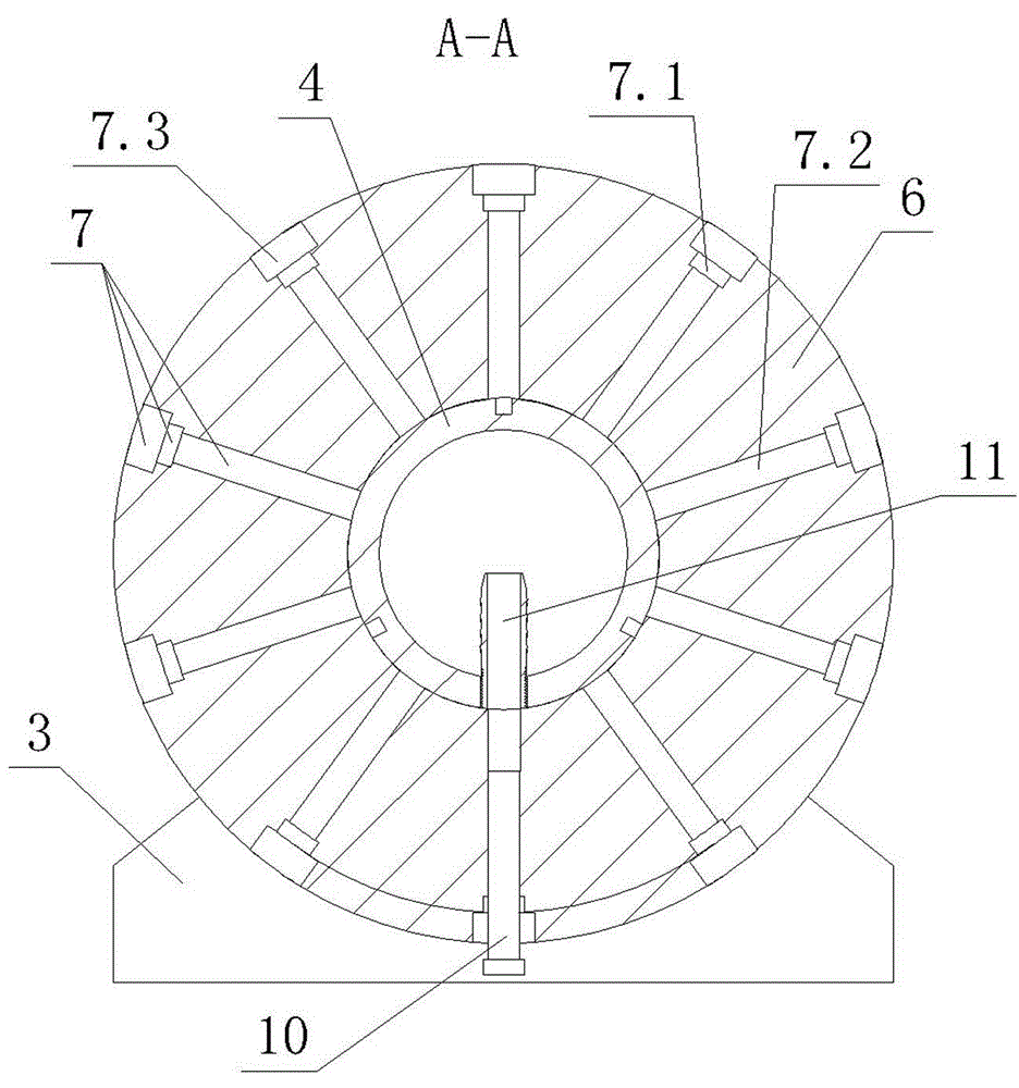
[0018] Such as figure 1 , figure 2 , image 3 , Figure 4 , Figure 5 As shown, the stamping die of the present invention includes a punch 1 and a die shell 2. The formwork 2 includes two supports 3 , a main shaft 4 , a pneumatic disc 5 and a drum 6 . The two ends of the main shaft 4 are respectively fixed to the two supports 3 , and the rotating drum 6 is provided with a central hole and the rotating drum 6 is rotatably fitted on the main shaft 4 through the central hole. The pneumatic disc 5 includes a disc shell 15 and an impeller 16 located in the disc shell 15. The disc shell 15 is composed of a peripheral wall and an end wall. Through the through hole, the end wall of the disc shell 15 is fixed to the main shaft 4. The impeller 16 is rotatably fitted on the main shaft 4, and the impeller 16 is limited in the circumferential direct...


PUM


Abstract

The invention discloses a stamping die which comprises a punch and a formwork. The formwork comprises two supports (3), a spindle (4), a pneumatic disc and a rotating drum (6). Two ends of the spindle (4) are fixed with the two supports (3), the rotating drum (6) is provided with a center hole, the spindle (4) is rotatably sleeved with the rotating drum (6) through the center hole, the pneumatic disc comprises a disc casing and an impeller located in the disc casing, an end wall of the disc casing is fixed with the spindle (4), the spindle (4) is rotatably sleeved with the impeller and is in circumferential limitation with the rotating drum (6), the rotating drum (6) is provided with a plurality of radial through holes (7), the punch is provided with a plurality of punching columns, the lower end of every punching column is provided with a hexagonal prism protrusion, all the punching columns are distributed in a row, the whole row of punching columns are opposite to a row of radial through holes (7) at the highest position of the rotating drum (6), and a circumferential wall of the disc casing is provided with a first nozzle for blowing blades of the impeller. The stamping die is quick in speed in the stamping process, high in efficiency, safe and convenient.

Description

technical field [0001] The invention relates to the technical field of molds, in particular to a stamping mold for stamping screws. Background technique [0002] The stamping die of the traditional stamping screw includes a lower die and an upper die. The upper end of the lower die is provided with a blind hole that matches the shape of the screw, that is, the lower die cavity. The lower end of the upper die is provided with cylindrical pits. The top is provided with hexagonal prism protrusions, and the cavity between the cylindrical recess and the hexagonal prism protrusions constitutes an upper die cavity that matches the shape of the head of the hexagon socket head screw, and the centerlines of the upper and lower die cavities coincide. Fix the lower mold, and put a round rod into the lower mold cavity. The length of the round rod is greater than the height of the lower mold cavity, and the upper mold and the punch are fixed. Drive the punch to make the two molds close to...

Claims


Application Information

Patent Timeline
IPC IPC(8): B21D37/10B21D53/24
Inventor 陆昱森
Owner XINGHUA TIEXIN ELECTRONICS ENG
Why Eureka
Try Eureka