Combined aircraft that generate greater lift

A combination of aircraft and lift technology, applied in the aviation field, can solve problems such as difficult development, and achieve the effects of easy production, easy mass production, and increased positive pressure power

Active Publication Date: 2016-06-29
朱晓义
View PDF5 Cites 0 Cited by
  • Summary
  • Abstract
  • Description
  • Claims
  • Application Information

AI Technical Summary

Problems solved by technology

It is necessary to find a greater source of lift and to completely change the structure of traditional aircraft, otherwise it will be difficult to achieve further development

Method used


Image

  • Combined aircraft that generate greater lift
  • Combined aircraft that generate greater lift
  • Combined aircraft that generate greater lift

Examples


Embodiment Construction

[0027] In order to describe the technical content, structural features, achieved goals and effects of the present invention in detail, the following will be described in detail in conjunction with the embodiments and accompanying drawings.

[0028] First summarize the technical scheme of the present invention as a whole:

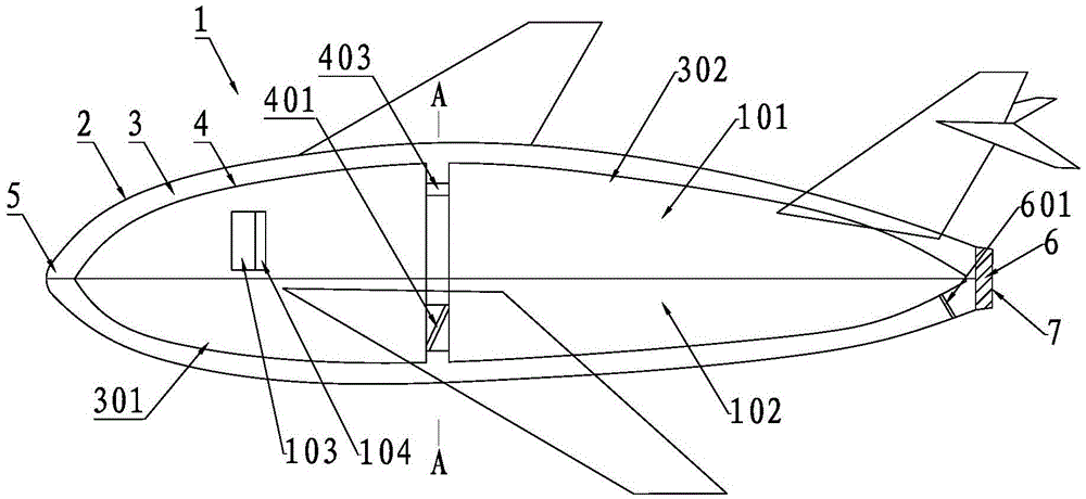
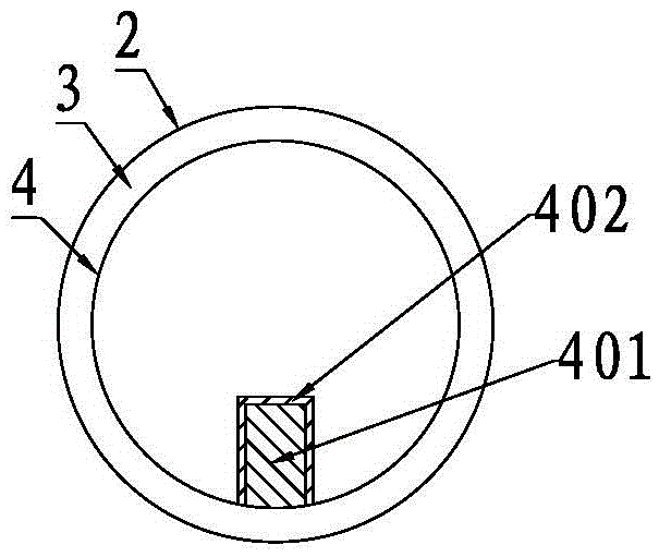
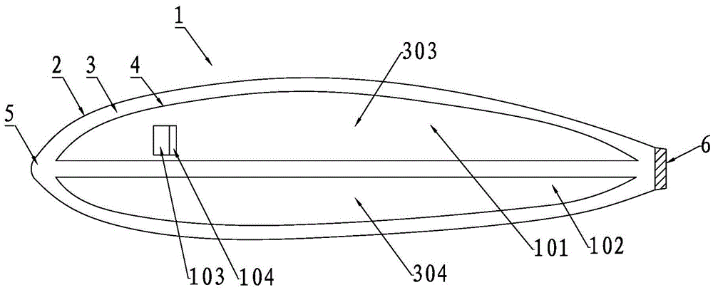
[0029] 1. The aircraft of Embodiments 1 to 7 has a plurality of inlets on the shell and communicates with the fluid passages. Under the action of the huge suction of the engine, the high-speed fluid in the fluid passages passes around each carrying cabin, so that each carrying cabin Generate lift and extend to the aircraft shell connected with it to form a high-speed fluid layer located in the upper half of the aircraft and a low-speed fluid layer located in the lower half. The difference in flow velocity between the fluid layers produces greater lift.

[0030] 2. The eighth embodiment is that a plurality of carrying compartments are combined into an aircraf...


PUM


Abstract

The invention discloses a combined aircraft that generates greater lift. The combined aircraft that generates greater lift includes a shell and an engine. The surface of the shell is provided with a plurality of inlets for introducing airflow. There is a fluid channel communicating with the outside world through the inlet, and the fluid channel divides the inside of the shell into a plurality of independent carrying compartments that can generate lift; the suction port of the engine communicates with the inlet through the fluid channel , the exhaust port of the engine communicates with the outside world, and a plurality of said carrying compartments are combined into aircrafts with different purposes. Its beneficial effect is that the suction of the engine makes the fluid flowing at high speed in the fluid channel pass around each carrying cabin at a high speed and communicate with the upper half shell of the aircraft to form a high-speed fluid layer, which is in a natural position with the lower half shell. A pressure difference is created between the low flow velocities in the state, so that each capsule can generate lift respectively, so that the interior of the aircraft can generate lift.

Description

technical field [0001] The invention relates to the field of aviation, in particular to a combined aircraft generating greater lift. Background technique [0002] Now some fixed-wing aircraft, such as passenger planes, transport planes, bombers, fighter jets, unmanned aerial vehicles, etc., because the fuselage is a closed whole, and the path length between the arc surface and the plane of the upper and lower surfaces of the wing is not much different, so the The traditional aircraft structure with wings as the only source of lift and a closed fuselage has hardly changed in more than a hundred years, and has become a shackle for the development of the aviation industry. It is necessary to find a greater source of lift and to completely change the structure of traditional aircraft, otherwise it will be difficult to obtain further development. [0003] The inventor has obtained more than ten invention patents in this field, among which the Chinese invention patent No. 2011100...

Claims


Application Information

Patent Timeline
Patent Type & Authority Patents(China)
IPC IPC(8): B64C39/00B64C3/14
Inventor 朱晓义
Owner 朱晓义
Why Eureka
Try Eureka