System and method for coordinating power management of fpga chip and bmc chip on atca blade

A power management system, BMC chip technology, applied in the computer field, can solve problems such as chip damage, and achieve the effect of simple troubleshooting

Active Publication Date: 2017-01-11
DAWNING INFORMATION IND BEIJING +1
View PDF5 Cites 0 Cited by
  • Summary
  • Abstract
  • Description
  • Claims
  • Application Information

AI Technical Summary

Problems solved by technology

Otherwise, there is a high chance that the chip will be damaged

Method used


Image

  • System and method for coordinating power management of fpga chip and bmc chip on atca blade
  • System and method for coordinating power management of fpga chip and bmc chip on atca blade

Examples


Embodiment Construction

[0027] The present invention will be described in further detail below in conjunction with the accompanying drawings.

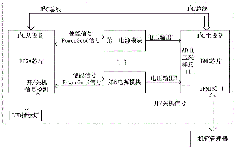
[0028] like figure 1 , the present invention provides a cooperative power management system for an FPGA chip on an ATCA (Advanced Telecom Computing Architecture) blade and a BMC (Baseboard Management Controller) chip, the system includes an FPGA chip, a BMC chip, N power modules and chassis management device; the enabling pins and PowerGood pins of N power modules are respectively connected to the IO pins of the FPGA chip, and the output ends of the N power modules are all connected to the AD sampling interface of the BMC chip, and the FPGA chip Communicate with the BMC chip through the I2C bus; the chassis manager is bidirectionally connected with the BMC chip.

[0029] The BMC chip and the FPGA chip are respectively an I2C master device and an I2C slave device, and the BMC chip accesses a power-on state register inside the FPGA chip through the I2C bus.

...


PUM


Abstract

The invention provides a system and a method for collaborative power management of an FPGA (field programmable gata array) chip and a BMC (baseboard management controller) chip used on an ATCA (advanced telecom computing architecture) blade. The system comprises the FPGA chip, the BMC chip, N power modules and a cabinet manager. Enable pins and Power Good pins of the N power modules are respectively connected with IO (in-out)pins of the FPGA chip, output ends of the N power modules are all connected on an AD (analog-digital) sampling interface of the BMC chip, and the FPGA chip and the BMC chip are communicated through a I2C (inter-integrated circuit) bus. The cabinet manager and the BMC chip are connected bidirectionally. By the aid of the system and the method, whether or not power-on of the FPGA chip is normal is indicated according to state of an LED (light-emitting diode) indicator light, searching power failure by using hardware tools can be further avoided as far as possible, so that troubleshooting becomes simple and high-efficient.

Description

technical field [0001] The invention belongs to the technical field of computers, and in particular relates to a cooperative power management system and method for an FPGA chip and a BMC chip on an ATCA blade. Background technique [0002] On a relatively complex ATCA blade, each power supply between each core chip and each chip itself requires a certain power-on sequence to work normally. Usually, we use a programmable device to control the output enable terminal of the power module, and achieve the power-on sequence requirements between various power supplies through different delays. [0003] Using a programmable device to control the power-on output is mainly to control the output enable terminal of the power module, and turn on the output of each power module at different times. In some chips, the power-on sequence requirements between the various power supplies are relatively strict, and the two power supplies with power-on sequence cannot be inverted. Otherwise, the...

Claims


Application Information

Patent Timeline
Patent Type & Authority Patents(China)
IPC IPC(8): G06F11/30
Inventor 袁海滨张克功邵宗有沙超群郑臣明王晖
Owner DAWNING INFORMATION IND BEIJING
Why Eureka
Try Eureka