Method for carrying out automatic powder charging by rapidly positioning blast hole under shaft

A blasting hole and charge technology, which is applied in image data processing, instruments, blasting, etc., can solve problems such as poor safety, high labor intensity, and long time for hole alignment

Active Publication Date: 2014-02-26
XIAN UNIV OF SCI & TECH +1
View PDF3 Cites 15 Cited by
  • Summary
  • Abstract
  • Description
  • Claims
  • Application Information

AI Technical Summary

Problems solved by technology

[0003] Aiming at the problems existing in the prior art, the present invention provides a method for quickly locating blastholes in the mine for automatic charge charging. In this method, a structured light vision system is installed on the charge mechanical arm, and the charge charge is controlled by the structured light vision system. The movement of the mechanical arm can automatically control the pipe feeding device at the end of the mechanical arm to align the holes, and the accuracy of the alignment is high. Facing the harsh conditions of the underground, it can complete the automatic positioning from one blasthole to another, which not only solves the problem of It solves the problems of high labor intensity and poor safety of the workers who charge the powder manually in the traditional way, and also solves the problems of the difficulty in aligning the holes, the cumbersome operation process and the long time for the holes to be manually controlled by the mechanical arm of the charge.

Method used


Image

  • Method for carrying out automatic powder charging by rapidly positioning blast hole under shaft
  • Method for carrying out automatic powder charging by rapidly positioning blast hole under shaft
  • Method for carrying out automatic powder charging by rapidly positioning blast hole under shaft

Examples


Embodiment Construction

[0034] The present invention will be further described in detail below in conjunction with the accompanying drawings and specific embodiments.

[0035] Before the holes are aligned, the distribution positions of the blastholes have been determined, that is, the layout of the blastholes is known from the blasting design. The blastholes in this embodiment are fan-shaped upwards, and the structured light vision system and the mechanical arm have been debugged and installed.

[0036] The method for automatically charging explosives by adopting the described downhole rapid positioning of blastholes comprises the following steps:

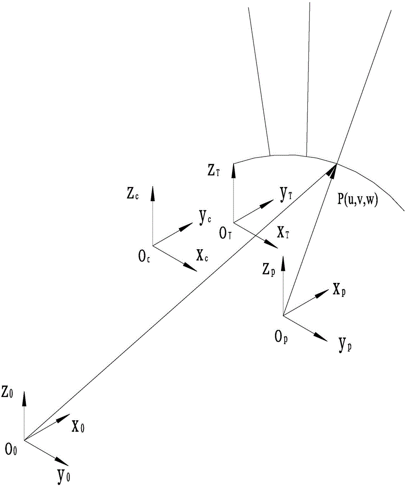
[0037] Step 1: Determine the coordinate system of the job site

[0038] The job site coordinate system (such as figure 1 shown) including the blast hole coordinate system O P -x p the y p z p , Manipulator base coordinate system O 0 -x 0 the y 0 z 0 , The coordinate system O of the pipe delivery device T -x T the y T z T and the camera coordi...


PUM


Abstract

The invention provides a method for carrying out automatic powder charging by rapidly positioning a blast hole under a shaft and belongs to the technical field of mine blasting. According to the method, the movement of a powder charging mechanical arm is controlled by a structured light visual system and holes can be aligned automatically; the hole alignment precision is high and automatic positioning from one blast hole to another blast hole can be finished. The method comprises the following steps: determining a working field coordinate system; selecting a blast hole P1 needing to be positioned to finish hole alignment and powder charging work of the blast hole P1; automatically positioning a second blast hole P2 to finish the hole alignment and powder charging work of the blast hole P2; finishing the hole alignment and powder charging work of a third blast hole P3 and a fourth blast hole P4 by referring the hole alignment and powder charging step of the second blast hole P2; calculating a transformational matrix from a blast hole coordinate system to a mechanical arm base coordinate system according to a corresponding relation of position vectors of the four blast holes by the structured light visual system; revising the transformational matrix and utilizing the revised transformational matrix to position subsequent blast holes.

Description

technical field [0001] The invention belongs to the technical field of mine blasting, and in particular relates to a method for quickly locating blastholes underground for automatic charging. Background technique [0002] In mine blasting operations, loading explosives in blastholes is a very important link. At this stage, there are mainly two ways to load explosives in blastholes. One is to fill explosives in a purely manual way. Sticks are used to stuff finished explosives into the blast hole, or workers can stuff the drug delivery tube into the blast hole to fill the bulk explosives, but pure manual charging makes the labor intensity of workers very high and the safety is poor; the other is through Manually control the explosive charging mechanical arm, and send the drug delivery tube into the blast hole through the tube feeding device at the end of the mechanical arm to fill the bulk explosives. However, this method requires a very high technical level of the operator. I...

Claims


Application Information

Patent Timeline
Patent Type & Authority Applications(China)
IPC IPC(8): G06T7/00F42D1/08
Inventor 王燕孙伟博李泽华佟彦军李孝林陈永兵张东升王洪强吕鑫解乐杜欣
Owner XIAN UNIV OF SCI & TECH
Why Eureka
Try Eureka