Straw chopping and wind blowing directional throwing device

A technology of spreading device and air delivery, which is applied in the direction of cutters, crop processors, agricultural machinery and implements, etc., to achieve the effects of easy processing, high operating efficiency, and increased crop yield

Active Publication Date: 2015-08-26
HUNAN AGRICULTURAL UNIV
View PDF6 Cites 0 Cited by
  • Summary
  • Abstract
  • Description
  • Claims
  • Application Information

AI Technical Summary

Problems solved by technology

[0003] The technical purpose of the present invention is to provide a straw chopping and air blowing directional throwing device to solve the defects in the use of stubble straw in the existing rice fields. While chopping the straw, use the fan to directly throw the straw back to the field, which can be assembled into the planting plant. Shallow plowing, sowing, shredding and scatter returning to the field can be realized at one time on the machine

Method used


Image

  • Straw chopping and wind blowing directional throwing device
  • Straw chopping and wind blowing directional throwing device
  • Straw chopping and wind blowing directional throwing device

Examples


Embodiment

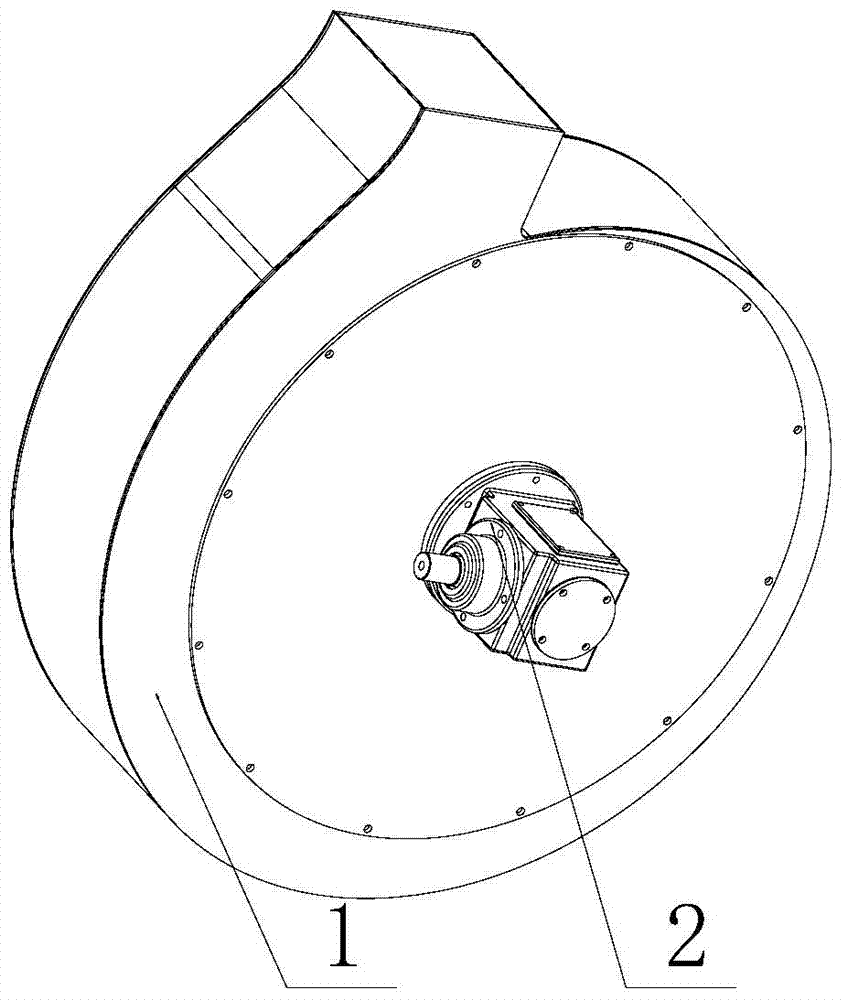
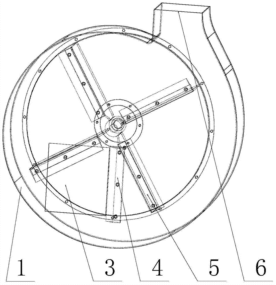
[0027] see figure 1 with figure 2 , the straw chopping and air blowing directional throwing device, including a casing 1, a fixed knife 4, a moving knife assembly 5 and an air blowing directional throwing device 8, the side of the casing 1 is provided with a feeding port 3 for feeding straw, and the fixed knife 4. It is arranged inside the casing 1 on the edge of the feeding port 3. The moving knife assembly 5 includes a fan blade 55 and a moving knife 53. The moving knife 53 is fixed on the side of the rotating fan blade and performs shearing motion with the fixed knife 4. The position of the air outlet of the fan blade on the casing 1 is provided with a throwing port 6 , and the air blowing directional throwing device 8 is docked with the throwing port 6 .

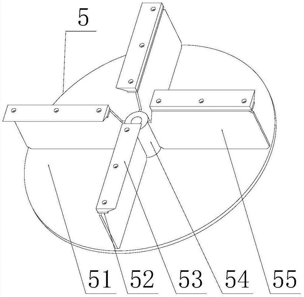
[0028] see further image 3 , Figure 4 with Figure 5 , the four blades 55 are vertically fixed and welded on the fan flange 51 with the fan shaft sleeve 54 as the center, the casing 1 is provided with a transmissi...


PUM


Abstract

The invention discloses a straw cutting and pneumatic-conveying oriented throwing device. The straw cutting and pneumatic-conveying oriented throwing device comprises a shell, a fixed knife, a movable knife assembly and a pneumatic-conveying oriented throwing device body. A feed inlet for feeding straw is arranged on the shell. The fixed knife is arranged on the portion, at the edge of the feed inlet, of the inner side of the shell. The movable knife assembly comprises a draught fan blade and a movable knife. The movable knife is fixedly arranged on the rotating draught fan blade, and shearing motion is done by the movable knife and the fixed knife together. A throwing opening is formed in the portion, at a draught fan blade air outlet, on the shell, and the pneumatic-conveying oriented throwing device body is in butt joint connection with the throwing opening. The rotating blade is adopted to drive the shearing motion of the fixed knife and the movable knife to cut the straw, and the cut straw can be thrown out through the throwing opening along the pneumatic-conveying oriented throwing device body by high-speed airflow generated when the blade rotates. The straw cutting and pneumatic-conveying oriented throwing device is simple in structure, easy to machine, high in working efficiency and good in quality; broken straw remaining after stubble cleaning can be thrown into fields in an oriented mode, preservation of soil moisture and heat of crops can be effectively achieved, and the yield of the crops can be improved.

Description

technical field [0001] The invention belongs to parts of a planter, and in particular relates to a straw chopping and air blowing directional throwing device. Background technique [0002] The existing seeders mainly use the rotary tillage device to plow and bury the stubble left in the field. Firstly, it can achieve the effect of moisture conservation, heat preservation, and favorable emergence of crops. Second, after returning to the field, it can also be used as fertilizer for later crops to improve the soil. Soil quality, but due to the high stubble left after rice harvest in southern paddy fields, the soil is heavy and compacted, it is easy to wind the rotary tiller shaft, plow and other operating tools when turning the soil before sowing, and the tilling soil before sowing will entangle grass and mud on the tillage parts It will greatly affect the normal operation of the seeder, and the effect of returning to the field is not good; and the complete straw decay process ...

Claims


Application Information

Patent Timeline
Patent Type & Authority Patents(China)
IPC IPC(8): A01D82/00
Inventor 吴明亮邱进王晓钰石增祥
Owner HUNAN AGRICULTURAL UNIV
Why Eureka
Try Eureka