
Spinning type reinforcing steel bar automatic straightening machine

An automatic adjustment and spinning technology, applied in the field of steel bar processing, can solve the problems of heavy operating costs, fast loss of straightening blocks, and many wearing parts, and achieves the effect of simple and reasonable structure, extended service life, and easy operation and maintenance.

Active Publication Date: 2014-03-05
冯广建
View PDF2 Cites 3 Cited by
  • Summary
  • Abstract
  • Description
  • Claims
  • Application Information

AI Technical Summary

Problems solved by technology

The current common straightening methods are: 1), use horizontal and vertical pressure rollers to straighten the steel bars, this method cannot effectively straighten the universally twisted steel bars; 2), use the rotating frame to set the rollers to straighten the steel bars , this method is disclosed in the patent document "CN200520102272.9-straightening roller device", and the rollers in the rotating frame can effectively straighten the steel bars in multiple directions, but this method automatically feeds the steel bars and different wire diameters It is inconvenient to straighten the steel bar, and the straightening effect is not ideal; 3), use the straightening block arranged in the rotating adjustment cylinder to straighten the steel bar, this method is described in the patent document "CN200520102271. It is disclosed in "Straightening Cylinder" that the straightening block in this method has great friction damage to the surface of the steel bar and the noise is large, and because of the large friction, the straightening block wears out quickly, resulting in many wearing parts and heavy operating costs. Automatic feeding and efficiency Neither is ideal

Method used


Image

  • Spinning type reinforcing steel bar automatic straightening machine
  • Spinning type reinforcing steel bar automatic straightening machine
  • Spinning type reinforcing steel bar automatic straightening machine

Examples


Embodiment Construction

[0025] The spinning type steel bar automatic straightening machine of the present invention will be described in further detail below in conjunction with the accompanying drawings and preferred embodiments.

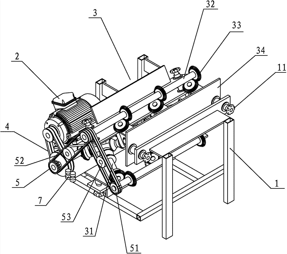
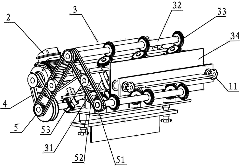
[0026] refer to figure 1 , The preferred embodiment provided by the present invention is a spinning type steel bar automatic straightening machine, which includes a frame 1 and a motor 2, and a straightening mechanism 3 driven by the motor 2 is mounted on the frame 1.

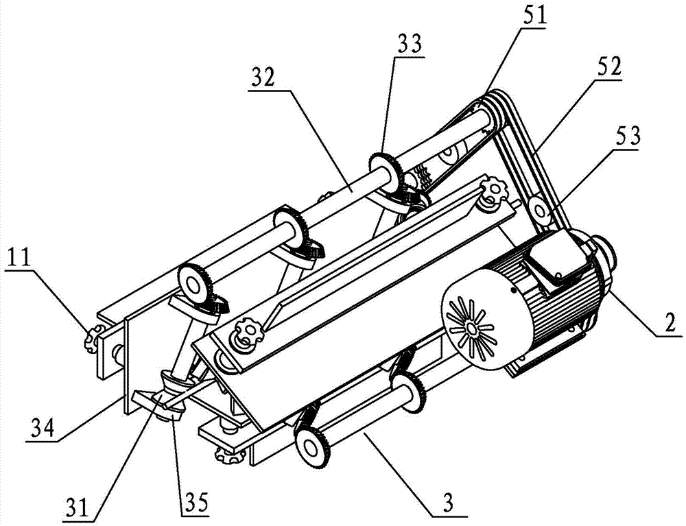
[0027] The straightening mechanism 3 includes at least one group of oblique rollers, each group of oblique rollers is made up of a plurality of oblique rollers 31 in contact with the steel bar 6, refer to Figure 4 to Figure 6 In this embodiment, three groups of oblique rollers are preferably used, and each group is composed of three oblique rollers 31 uniformly distributed on the radial periphery of the steel bar. refer to Figure 5 , the oblique rollers 31 are arranged sequentially along the axial dire...


PUM


Abstract

The invention discloses a spinning type reinforcing steel bar automatic straightening machine. The spinning type reinforcing steel bar automatic straightening machine comprises a machine frame and a drive device, wherein a straightening mechanism driven by the drive device is arranged on the machine frame, the straightening mechanism comprises at least one set of inclined rotating idler wheels, each set of inclined rotating idler wheels are composed of a plurality of inclined rotating idler wheels making contact with a reinforcing steel bar, the inclined rotating idler wheels are sequentially arranged in the axial direction of the reinforcing steel bar, the inclined rotating idler wheels in the same set are evenly distributed on the radial periphery of the reinforcing steel bar in the circumferential direction, the inclined rotating idler wheels incline relative to the axial direction of the reinforcing steel bar, and the drive device drives the inclined rotating idler wheels to rotate and to straighten and convey the reinforcing steel bar. The spinning type reinforcing steel bar automatic straightening machine is reasonable in structure, capable of effectively straightening and automatically conveying the reinforcing steel bar at the same time, and good in straightening effect.

Description

technical field [0001] The invention relates to the field of steel bar processing, in particular to a spinning type automatic straightening machine for steel bars. Background technique [0002] At present, the steel bars used in construction projects are usually first cut by straightening and cutting the disc-shaped steel bars produced by the steel factory, and then bent into the required shape before they can be used. The current common straightening methods are: 1), use horizontal and vertical pressure rollers to straighten the steel bars, this method cannot effectively straighten the universally twisted steel bars; 2), use the rotating frame to set the rollers to straighten the steel bars , this method is disclosed in the patent document "CN200520102272.9-straightening roller device", and the rollers in the rotating frame can be used to effectively straighten the steel bars in multiple directions, but this method automatically feeds the steel bars and different wire diame...

Claims


Application Information

Patent Timeline
Patent Type & Authority Applications(China)
IPC IPC(8): B21F1/02B21F23/00
Inventor 冯广建
Owner 冯广建
Learn More