Power Generation Welding Unit

A technology for electric welding units and generators, applied in welding equipment, auxiliary welding equipment, welding/cutting auxiliary equipment, etc., can solve the problems of increased maintenance costs, short service life, chassis vibration, etc., and achieves good cooling effect. Conducive to heat dissipation, the effect of heat dissipation

Active Publication Date: 2016-06-15
上海气焊机厂有限公司
View PDF6 Cites 2 Cited by
  • Summary
  • Abstract
  • Description
  • Claims
  • Application Information

AI Technical Summary

Problems solved by technology

[0002] The power generation electric welding unit is used for welding, and it can realize welding without external power supply. It can be used in field operations, inconvenient electricity consumption, pipeline welding, power failure emergency welding, engineering construction, etc., which has great convenience. , has been widely used. The chassis of the power generation welding machine is composed of heating components such as inductors and rectifiers. When it is working, it needs to be cooled. The traditional power generation welding machine is equipped with a fan on the top of the chassis, and the internal heating components are cooled by the fan. and the motor for cooling. In the actual use process, it is prone to malfunction and damage to the equipment. At the same time, it increases the maintenance cost and causes inconvenience to the user. The power of this power generation welding machine should not be too high. When the power is high, the fan It cannot meet the heat dissipation requirements of the equipment, which has caused great restrictions on the power generation welding machine. In addition, the fan needs to run at high speed and has a short service life, which causes serious vibration of the chassis. In order to better dissipate heat, the traditional chassis adopts an open design. Rats and rain can easily enter the case, causing damage to the components in the case

Method used


Image

  • Power Generation Welding Unit
  • Power Generation Welding Unit
  • Power Generation Welding Unit

Examples


Embodiment Construction

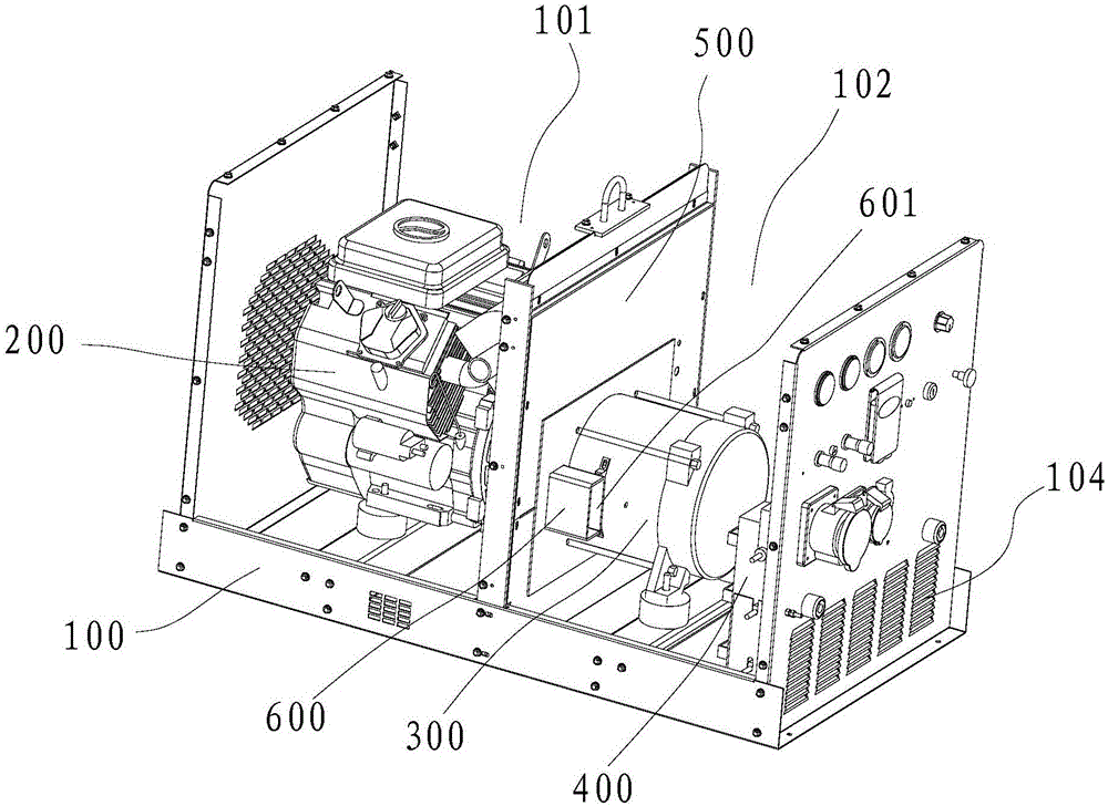
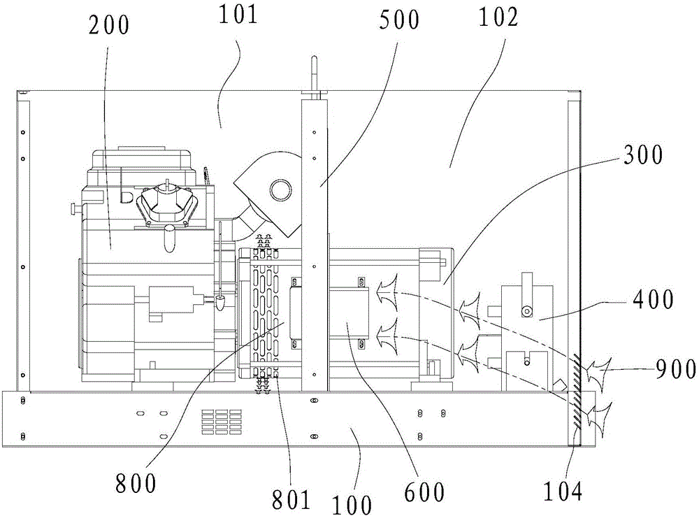
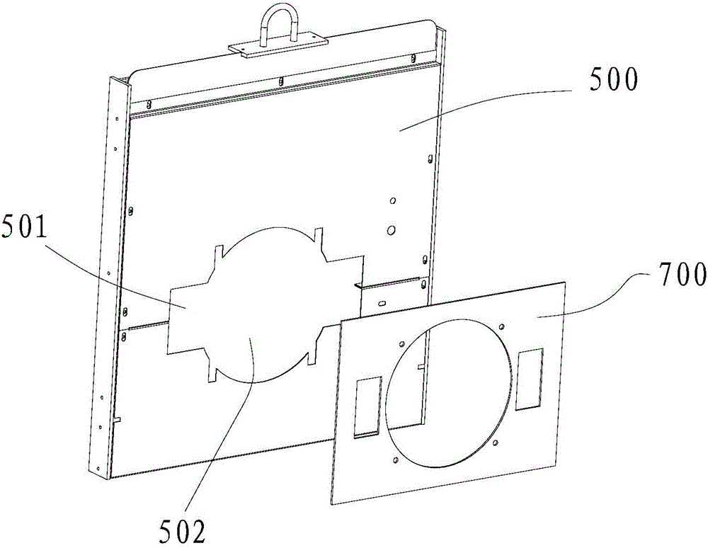
[0022] Embodiments of the present invention are described in detail below in conjunction with accompanying drawings:

[0023] like Figure 1-5 As shown, in an embodiment of the present invention, a power generation electric welding unit includes a chassis 100, an internal combustion engine 200, a generator 300, a heating element 400, a centrifugal fan, and an air duct 600. The heating element 400 includes a reactance and a rectification assembly , the chassis 100 includes a first installation area 101 and a second installation area 102, the first installation area 101 and the second installation area 102 are separated by a partition 500, the internal combustion engine 200 is installed in the first installation area 101, and the generator 300 1. The heating element 400 is installed in the second installation area 102, the output end of the internal combustion engine 200 is connected to the generator 300, the heating element 400 is electrically connected to the generator 300, th...


PUM


Abstract

The invention discloses an electricity-generating electric welding unit which comprises a machine case, an internal-combustion engine, a generator, a heating element, a centrifugal fan and air channels. The machine case comprises a first installing region and a second installing region which are isolated through a partition plate, the internal-combustion engine is installed in the first installing region, the generator and the heating element are installed in the second installing region, the output end of the internal-combustion engine is connected with the generator, the heating element is electrically connected with the generator, and the centrifugal fan is arranged at the output end of the internal-combustion engine in a sleeved mode. At least two through holes are formed in the partition plate, the air channels are installed in the through holes, matched with the through holes and communicated with an air inlet of the centrifugal fan, and an air outlet of the centrifugal fan is led outside the machine case. The surface temperature of the internal-combustion engine is high, the machine case is divided into two regions which are separated by the partition plate, accordingly heat emitted by the internal-combustion engine can be prevented from being transferred to the generator and the heating element, and good refrigeration effect is achieved.

Description

technical field [0001] The invention relates to the technical field of electric welding machines, in particular to a generating electric welding unit. Background technique [0002] The power generation electric welding unit is used for welding, and it can realize welding without external power supply. It can be used in field operations, inconvenient electricity consumption, pipeline welding, power failure emergency welding, engineering construction, etc., which has great convenience. , has been widely used. The chassis of the power generation welding machine is composed of heating components such as inductors and rectifiers. When it is working, it needs to be cooled. The traditional power generation welding machine is equipped with a fan on the top of the chassis, and the internal heating components are cooled by the fan. and the motor for cooling. In the actual use process, it is prone to malfunction and damage to the equipment. At the same time, it increases the maintenanc...

Claims


Application Information

Patent Timeline
Patent Type & Authority Patents(China)
IPC IPC(8): B23K37/00
CPCB23K37/00B23K37/003
Inventor 舒振宇丁书才
Owner 上海气焊机厂有限公司
Why Eureka
Try Eureka