LCD module

A technology of liquid crystal display modules and liquid crystal display panels, which is applied in the direction of lighting devices, optics, light sources, etc., can solve the problems of difficult heat dissipation of plasma light-emitting panels, and achieve the effects of improving heat dissipation efficiency, increasing manufacturing costs, and good light transmission

Inactive Publication Date: 2006-12-13
AU OPTRONICS CORP
View PDF0 Cites 0 Cited by
  • Summary
  • Abstract
  • Description
  • Claims
  • Application Information

AI Technical Summary

Problems solved by technology

[0010] In view of this, the object of the present invention is to provide a liquid crystal display module to solve the problem of difficult heat dissipation of the plasma light-emitting panel in the above-mentioned existing liquid crystal display module

Method used


Image

  • LCD module
  • LCD module
  • LCD module

Examples


Embodiment Construction

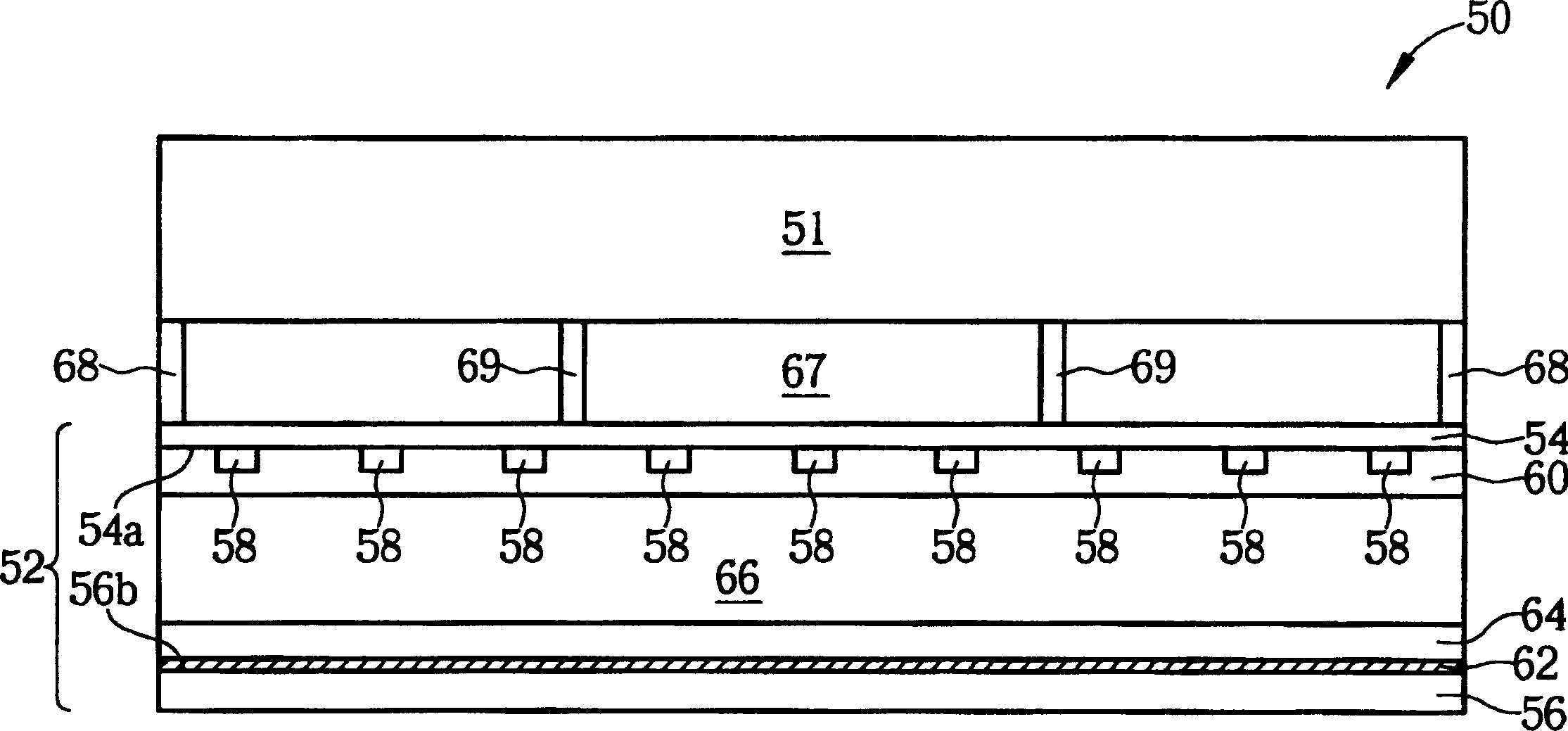
[0046] Please refer to image 3 , image 3It is a schematic cross-sectional view of the liquid crystal display module 50 in the first embodiment of the present invention. Such as image 3 As shown, the liquid crystal display module 50 has a liquid crystal display panel 51, a reflective plasma light-emitting panel 52 arranged below the liquid crystal display panel 51, and a reflective plasma light-emitting panel 52 arranged between the liquid crystal display panel 51 and the reflective plasma light-emitting panel 52. Insulation chamber67.

[0047] Such as image 3 As shown, the reflective plasma light-emitting panel 52 includes: a first substrate 54, a second substrate 56 parallel to the first substrate 54, and a plurality of electrodes 58 arranged on the lower surface 54a of the first substrate 54 and parallel to each other. , a dielectric layer 60 completely covering the surfaces of the plurality of electrodes 58, a reflective layer 62 disposed on an upper surface 56b of ...


PUM


Abstract

It is a LCD module set, which comprises a LCD panel, a electricity plasm light emitting panel under the LCD panel and heat insulation chamber located between the LCD panel and the electricity plasm light emitting panel. The electricity light emitting panel comprises first base plate, second base plate, multiple parallel electrodes, a dielectric layer, a fluorescence layer and a discharge space.

Description

technical field [0001] The present invention relates to a liquid crystal display module (LCD module), especially a liquid crystal display module with a heat insulation chamber. Background technique [0002] Plasma luminescent panel is a planar light emitter that generates light through gas discharge. It is composed of a plurality of discharge cells filled with inert gases such as neon (Ne) and xenon (Xe) or helium (He) and xenon. After being excited by an electric field, the inert gas in each discharge cell can generate ultraviolet light to irradiate on the phosphor on the surface of each discharge cell, and then the red, red, and Green and blue visible light, combined with the design of the driving circuit and image signal processing, and the visible light of these three primary colors are mixed to form a colorful picture, and according to the position of the phosphor, it can be divided into reflective electric There are two types of plasma luminescent panels and transmiss...

Claims


Application Information

Patent Timeline
Patent Type & Authority Patents(China)
IPC IPC(8): G02F1/13357H05B33/14G02F1/1335H05B33/00
Inventor 隋寿龄苏耀庆
Owner AU OPTRONICS CORP
Why Eureka
Try Eureka