Solar heat collection system for sloping roof and building

A technology of solar heat collection and inclined planes, which is applied in the field of solar heat collection systems, can solve the problems of metal brackets not being firmly fixed, high manufacturing and installation costs, and easy to be blown down by strong winds, so as to save installation consumables, improve installation efficiency, and reduce construction costs. cost effect

Pending Publication Date: 2022-06-17
LONGGUANGTIANXU SOLAR ENERGY ZHUCHENG +1
View PDF0 Cites 0 Cited by
  • Summary
  • Abstract
  • Description
  • Claims
  • Application Information

AI Technical Summary

Problems solved by technology

[0003] 1. A modular solar panel is about 2 square meters. Each solar panel is composed of heat absorbing panels, frames, tempered glass panels, thermal insulation materials and circulation pipes, which leads to high manufacturing and installation costs.
[0004] 2.

Method used


Image

  • Solar heat collection system for sloping roof and building
  • Solar heat collection system for sloping roof and building
  • Solar heat collection system for sloping roof and building

Examples


Embodiment 1

[0028] In an exemplary embodiment of the present invention, as Figure 1-Figure 4 As shown, a solar thermal collection system for sloped roofs is provided.

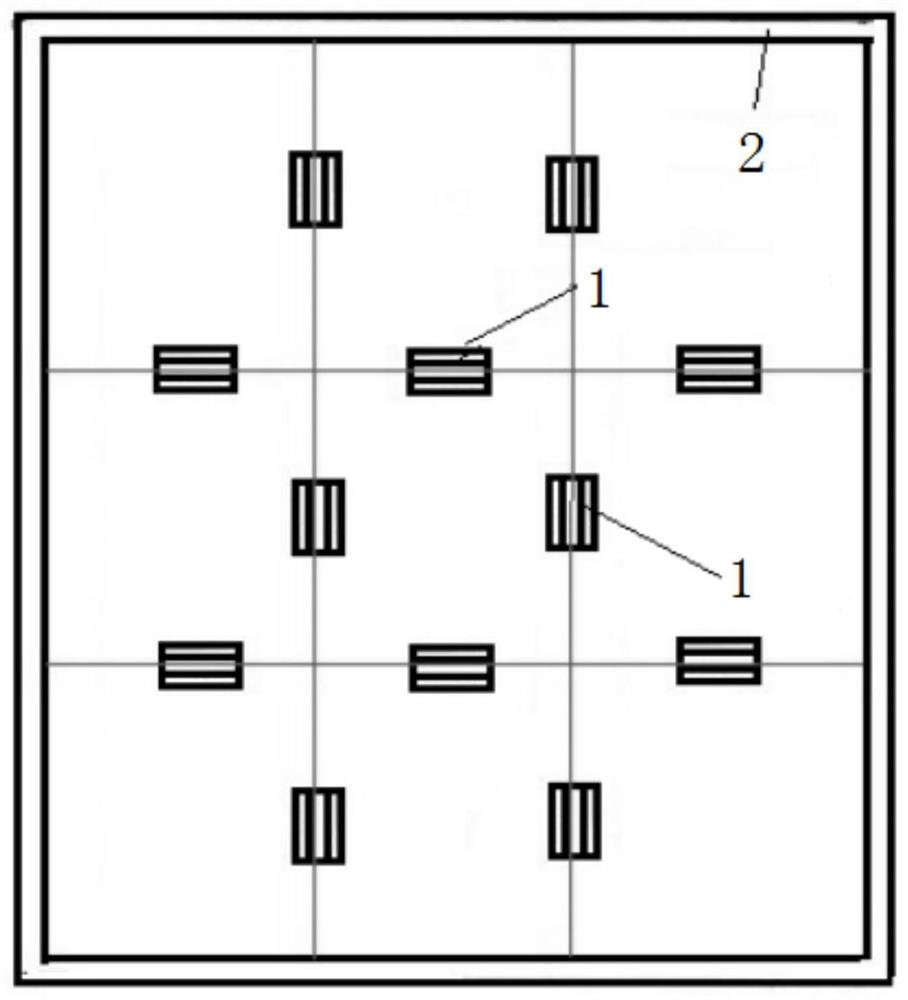
[0029] see Figure 1-Figure 3 As shown, an embodiment of the present invention provides a solar heat collection system for a sloping roof 3, the heat collection system includes a rectangular installation grid area arranged on the sloping roof 3, and the rectangular installation grid area is composed of a plurality of rectangular The unit grids are formed by splicing each other, and a fixing member 1 is provided on each side of each unit grid in the rectangular grid area.

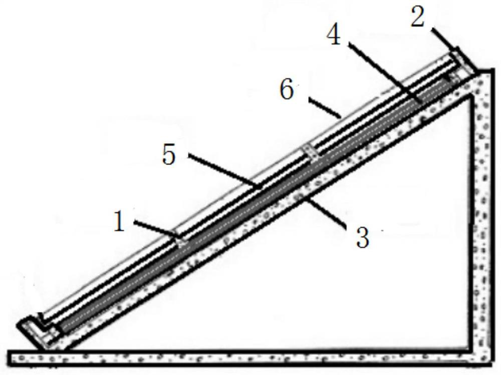
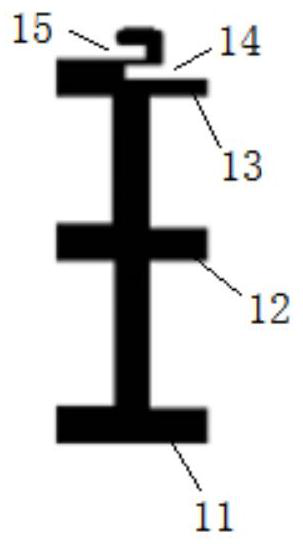
[0030] The fixing member 1 includes a bottom plate 11 , a middle plate 12 and a top plate 13 that are connected to each other. The bottom plate 11 , the middle plate 12 and the top plate 13 are parallel to each other. The bottom plate 11 is fixed on the sloping roof 3 . A heat insulating member 4 is installed in the area between the middle plate 12 an...

Embodiment 2

[0056] In another exemplary embodiment of the present invention, as Figure 1-Figure 4 As shown, a building is provided.

[0057] like Figure 1-Figure 4 As shown, the building utilizes the solar heat collection system for the pitched roof 3 in Embodiment 1, and the solar heat collection system for the pitched roof 3 is correspondingly installed on the roof 3 of the building.

[0058] The solar heat collection system is organically combined with the building, and the fixed part 1 in the heat collection system is connected with the sloped roof 3, which can be used to support the fixed light-transmitting part 6 and the fixed heat-absorbing part 5, so that the The material used for the vertical and horizontal support frame 2 in the solar heat collection system is greatly reduced, and the construction cost of the solar heat collection system is reduced.


PUM


Abstract

The invention relates to a solar heat collection system for a sloping roof and a building, and relates to the technical field of solar heat collection systems. Comprising a grid installation area formed by distributing a plurality of unit grids in a rectangular array, and at least one fixing piece is arranged between every two adjacent unit grids; the fixing piece comprises a bottom plate, a middle plate and a top plate which are sequentially connected, a heat insulation piece located in the unit grid is arranged between the bottom plate and the middle plate, the side, away from the bottom plate, of the middle plate is connected with a heat absorption piece, the heat absorption piece is provided with a circulating heat pipe, and the top plate is connected with a light-transmitting piece; in order to solve the problem that a solar heat collection system is not easy to install on an existing sloping roof, the solar heat collection system for the sloping roof is designed, the existing sloping roof can be directly used as a bearing layer, organic combination of the solar heat collection system and a building is achieved, and a fixing piece is directly fixed to the roof. The arrangement of extra frameworks, protective frames and other structures is reduced, the installation efficiency is improved, and installation consumables are saved.

Description

technical field [0001] The invention relates to the technical field of solar heat collection systems, in particular to a solar heat collection system and buildings for sloped roofs. Background technique [0002] At present, the construction of the solar heat collection system on the top of the building requires a plurality of modularly manufactured solar panels to be connected to each other, and to be fixed by installing metal brackets on the roof. Installing a solar collector system to absorb more heat has the following disadvantages: [0003] 1. A modular solar panel is about 2 square meters, and each solar panel is composed of heat-absorbing panels, frames, tempered glass panels, thermal insulation materials and circulation pipes, which leads to high manufacturing and installation costs. [0004] 2. It is not suitable for buildings with sloping roofs. If the metal brackets used to support these solar collector systems are not firmly fixed, unstable, and not durable, they...

Claims


Application Information

Patent Timeline
IPC IPC(8): F24S25/61F24S70/60F24S80/60H02S20/23E04B7/02E04D13/16
CPCF24S25/61F24S70/60F24S80/60H02S20/23E04B7/02E04D13/1662Y02E10/47Y02E10/50
Inventor 修大鹏邢作新张新恩钱启伟周吉学
Owner LONGGUANGTIANXU SOLAR ENERGY ZHUCHENG
Why Eureka
Try Eureka