
Powders pneumatic conveyor trough

A technology of pneumatic conveying and powder materials, which is applied in conveyors, conveying bulk materials, transportation and packaging, etc. It can solve the problems of powder materials being easily broken, low crushing rate, and many failures, and achieve the effect of not easily broken.

Inactive Publication Date: 2014-03-05
WUHU NEW UNIVERSAL ENVIRONMENTAL SCI TECH
View PDF5 Cites 0 Cited by
  • Summary
  • Abstract
  • Description
  • Claims
  • Application Information

AI Technical Summary

Problems solved by technology

[0002] When the powder is transported from the large silo to the sending tank, and from the silo to the powder scale, the powder is easily broken. Most of the existing conveying devices are more complicated and cause more failures. Therefore, a simple crushing rate is designed. Low powder conveying device is very necessary

Method used


Image

  • Powders pneumatic conveyor trough

Examples


Embodiment Construction

[0015] In order to deepen the understanding of the present invention, the present invention will be further described below in conjunction with examples, which are only used to explain the present invention and do not constitute a limitation to the protection scope of the present invention.

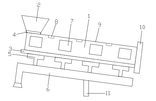
[0016] Such as figure 1 As shown, this embodiment provides a powder material pneumatic conveying tank, which includes a powder material chamber 1, a feed inlet 2 is provided on the upper left of the powder chamber 1, a filter plate 3 is provided below, and a feed inlet 2 is provided at the feed port 2. The material valve 4 is provided with a compressed air chamber 5 under the filter plate 3 , and a compressed air delivery pipe 6 is provided under the compressed air chamber 5 . The number of the compressed air chambers 5 is four and one is set every 80 cm. The shell of the powder chamber 1 is provided with an observation port 7 , a filling quantity sensor 8 is provided in the powder chamb...


PUM


Abstract

The invention aims to provide a powders pneumatic conveyor trough comprising a powders chamber. The powders pneumatic conveyor trough is characterized in that the left top of the powders chamber is provided with a feed hole, a filter plate is disposed below the powders chamber, the feed hole is provided with a feed valve, compressed gas chambers are arranged below the filter plate, and a compressed gas pipe is disposed below the compressed gas chambers. According to the conveyor trough which inclines, powder enters the powders chamber with a rubber-lined inner wall through the feed valve from a high position, and is conveyed by compressed gas at the bottom. The powders pneumatic conveyor trough is simple and has no need for moving parts, so that the powders crush rarely. A filling sensor is disposed inside the powders chamber; if filling quantity of the powders is high, the sensor allows the feed valve to control conveying speed of powders. Through the design of the powders pneumatic conveyor trough, smooth conveying of the powders is ensured; a telescopic support at the bottom end of the whole powders pneumatic conveyor trough allows tilting angle of the whole powders pneumatic conveyor trough to be adjustable, and tilt can be adjusted according to properties of the powders.

Description

technical field [0001] The invention relates to a powder conveying device, in particular to a powder pneumatic conveying tank. Background technique [0002] When the powder is transported from the large silo to the sending tank, and from the silo to the powder scale, the powder is easily broken. Most of the existing conveying devices are more complicated and cause more failures. Therefore, a simple crushing rate is designed. Low powder conveying device is very necessary. Contents of the invention [0003] The invention provides a device that only relies on air force to transport powder. The whole device is in an inclined shape. The powder is transported from a high place into a pneumatic conveying tank, and the powder is blown by the compressed air passing through the filter plate at the bottom. For conveying, and the powder air isolator is set at the lower end of the conveying trough, so that the powder can be conveyed out. [0004] The purpose of the present invention ...

Claims


Application Information

Patent Timeline
IPC IPC(8): B65G53/02
Inventor 蒋勇
Owner WUHU NEW UNIVERSAL ENVIRONMENTAL SCI TECH
Features
  • Generate Ideas
  • Intellectual Property
  • Life Sciences
  • Materials
  • Tech Scout
  • Unparalleled Data Quality
  • Higher Quality Content
  • 60% Fewer Hallucinations
Learn More