Spinning device for producing bright and clean yarn through spiral airflow

A technology of spiral air flow and smooth yarn, which is applied in the direction of continuous winding spinning machine, spinning machine, open-end spinning machine, etc. It can solve the irregular direction of the main air flow, reduce the braking effect of the traveler, and interfere with the steel wire Smooth loop sliding and other problems, to achieve the effect of reducing yarn hairiness, bright luster, and delicate fabric feel

Active Publication Date: 2014-03-05
DEZHOU HENGFENG TEXTILES
View PDF5 Cites 4 Cited by
  • Summary
  • Abstract
  • Description
  • Claims
  • Application Information

AI Technical Summary

Problems solved by technology

[0003] In the existing actual production, the method of reducing yarn hairiness is mainly by changing the steel ring in the spinning process, but the new steel ring and the steel ring that has entered the recession period make the yarn easy to fluff, because its rough sliding surface reduces The braking effect of the traveler is disturbed, the smooth sliding of the traveler is disturbed, and the hairiness of the yarn is increased instead; The spinning device did not get the expected effect when it was in use. The reason is that the provided multiple airflows intersect in the airflow groove, and the direction of the main airflow generated becomes irregular. When producing smooth yarns, it is still impossible Completely avoid yarn hairiness

Method used


Image

  • Spinning device for producing bright and clean yarn through spiral airflow
  • Spinning device for producing bright and clean yarn through spiral airflow
  • Spinning device for producing bright and clean yarn through spiral airflow

Examples


Embodiment Construction

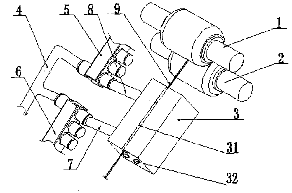
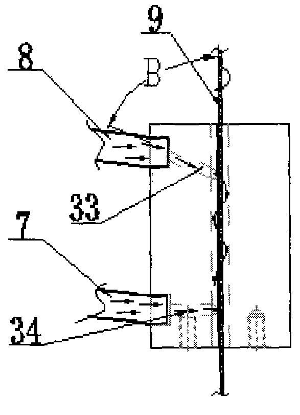
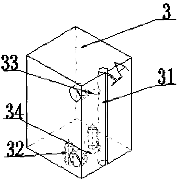
[0017] Referring to the accompanying drawings, a spinning device that utilizes spiral airflow to produce smooth yarn includes an upper twisting wheel 1 and a lower twisting wheel 2, and the upper twisting wheel 1 and the lower twisting wheel 2 pass through the yarn 9. The yarn 9 passes through the wire slot 31 in the spiral airflow generator 3. The wire slot 31 is a circular through hole with a diameter of 4 mm. The opening width of the outer axial direction of the wire slot 31 is 2 mm. There are two holes on the side of the airflow generator 3, which are respectively the upper spiral blow hole 33 and the lower horizontal blow hole 34. The air hole 33 and the horizontal air blow hole 34 are tangent to the inner wall of the wire groove 31, the spiral air blow hole 33 is connected with the external spiral air inlet pipe 8, and the horizontal air blow hole 34 is connected with the external horizontal air inlet pipe 7; On the basis of the line, the processing angle of the spiral a...


PUM

PropertyMeasurementUnit
diameteraaaaaaaaaa

Abstract

The invention belongs to the technical field of spinning equipment, and discloses a spinning device for producing bright and clean yarn through spiral airflow. The spinning device comprises an upper twisting wheel and a lower twisting wheel, wherein yarn penetrates through the space between the upper twisting wheel and the lower twisting wheel and then penetrates through a yarn passing groove of a spiral airflow generator. The side edge of the spiral airflow generator is provided with two holes which are respectively a spiral air-blowing hole in the upper portion and a horizontal air-blowing hole in the lower portion, wherein the spiral air-blowing hole is connected with an external spiral air inlet pipe, the horizontal air-blowing hole is connected with an external horizontal air inlet pipe, the spiral air-blowing hole is tangent with the inner wall of the yarn passing groove and is arranged at a certain angle so that the airflow can rotate spirally along the inner wall of the yarn passing groove to blow yarn hairness to be twisted in the twisting direction of the yarn, and then the yarn hairness is fixed along with the twisting of the yarn. By means of the spinning device for producing the bright and clean yarn through the spiral airflow, the amount of generated yarn hairness can be reduced obviously, the produced bright and clean yarn is smooth in surface and high in strength, and a fabric made from the bright and clean yarn is fine and smooth in hand feel, comfortable to ware and bright-colored in gloss.

Description

technical field [0001] The invention belongs to the technical field of spinning equipment, and in particular relates to a spinning device for producing smooth yarn by using a spiral airflow. Background technique [0002] Yarn hairiness refers to the fiber protrusions protruding from the surface of the yarn matrix. With the improvement of textile grades in the current society and the widespread use of shuttleless looms, the harm of yarn hairiness has become increasingly prominent. The fabric will have defects such as weft gaps, streaks, and cloud spots. Reducing yarn hairiness can make the fabric smooth, smooth, clear, and comfortable to wear. Yarn hairiness has become an important factor affecting fabric quality, so effectively reducing yarn hairiness Hairiness has become a focus of attention for textile companies. [0003] In the existing actual production, the method of reducing yarn hairiness is mainly by changing the steel ring in the spinning process, but the new steel...

Claims


Application Information

Patent Timeline
Patent Type & Authority Applications(China)
IPC IPC(8): D01H4/02
Inventor 苏建军刘玉庆许炳义张建明王志洪
Owner DEZHOU HENGFENG TEXTILES
Why Eureka
Try Eureka