
Pneumatic chuck remote control device

A technology of remote control device and pneumatic chuck, which is applied in the direction of drilling equipment, earthwork drilling, drill pipe, etc., and can solve the problem of many vulnerable parts of the chuck handle and chuck bracket, auxiliary functions that need to be further improved, and tooth plate pairing. Problems such as damage to the outer wall of the casing can be achieved to improve the safety factor and work efficiency, the structure is simple, and the effect of avoiding safety accidents is achieved.

Inactive Publication Date: 2014-03-05
CNPC BOHAI DRILLING ENG
View PDF8 Cites 5 Cited by
  • Summary
  • Abstract
  • Description
  • Claims
  • Application Information

AI Technical Summary

Problems solved by technology

However, the pneumatic chuck needs to manually move the pneumatic switch handle to loosen and clamp the casing, so some problems are exposed during use: first, the damage of the tooth plate to the outer wall of the casing is serious; second, the structural design is complicated , there are many wearing parts such as chuck handles and chuck brackets; third, the auxiliary functions need to be further improved; fourth, the operator must stand near the wellhead and frequently operate the wellhead chuck to complete the lifting and lowering operation

Method used


Image

  • Pneumatic chuck remote control device
  • Pneumatic chuck remote control device

Examples


Embodiment Construction

[0015] Below in conjunction with accompanying drawing and specific embodiment the present invention is described in further detail:

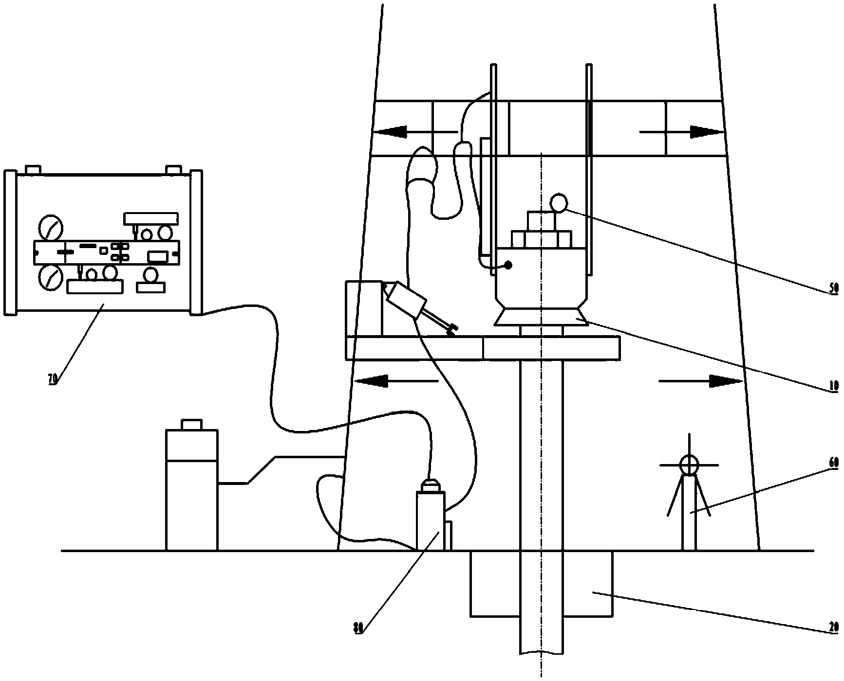
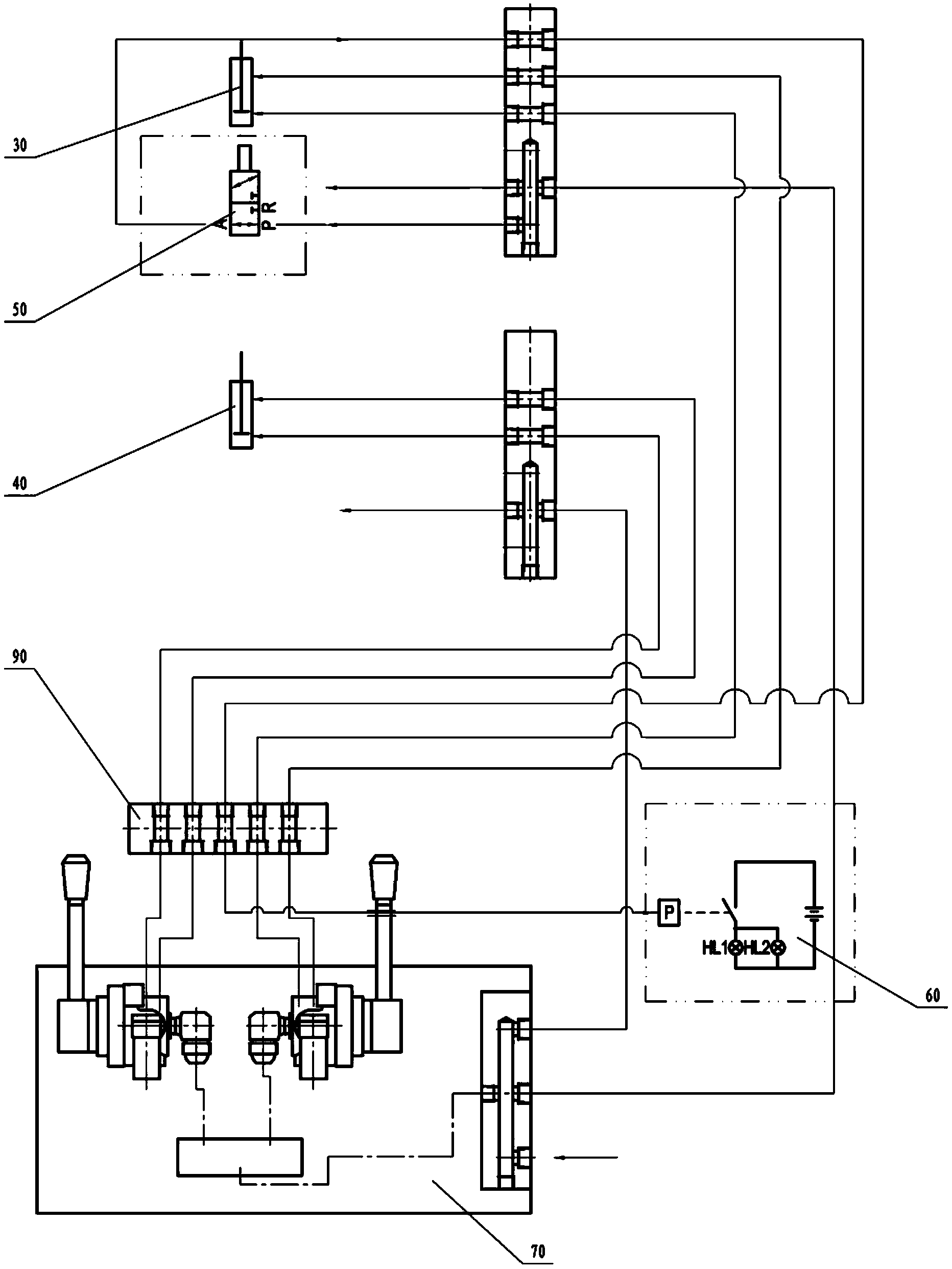
[0016] Such as figure 1 and figure 2 As shown, the pneumatic chuck remote control device of the present invention includes an upper chuck 10, a lower chuck 20, an upper chuck control cylinder 30, a lower chuck control cylinder 40, a thrust sensor 50, an upper chuck alarm device 60, Control surface panel 70, remote control box 80 and coupling block 90, described upper chuck control cylinder 30, lower chuck control cylinder 40 are respectively installed on the side of described upper chuck 10 and lower chuck 20, and control cylinder is installed on The outer surface of the chuck, and the cylinder is equipped with a shield, which is beneficial to protect the control cylinder; prevent the control cylinder from being damaged during installation, and at the same time, the internal structure and mechanical properties of the chuck will not be changed....


PUM


Abstract

The invention discloses a pneumatic chuck remote control device. The pneumatic chuck remote control device comprises an upper chuck, a lower chuck, an upper chuck control air cylinder, a lower chuck control air cylinder, a thrust sensor, an upper chuck alarm device, a control panel, a remote control cabinet and a connecting block. The upper chuck control air cylinder and the lower chuck control air cylinder are arranged on a side face of the upper chuck and a side face of the lower chuck respectively, protective covers are additionally arranged outside the upper chuck control air cylinder and the lower chuck control air cylinder, the thrust sensor is arranged on a top cover of the upper chuck, an alarm lamp in the alarm device is arranged into a driller room, the control panel is arranged in the remote control cabinet, and the control panel is connected with the upper chuck control air cylinder and the lower chuck control air cylinder through the connecting block and an air pressure pipeline respectively. The pneumatic chuck remote control device has the advantages that the chucks tightly clamp casing strings or release the casing strings through the remote control device, the pneumatic chuck remote control device can be operated by hand and controlled automatically and is simple in structure and convenient to operate, labor intensity of workers is relieved, and the safety coefficient of well mouth operation and work efficiency of well mouth operation are improved.

Description

technical field [0001] The invention relates to an oil field construction machine, in particular to a remote control device for upper and lower pneumatic chucks in casing casing construction in well drilling. Background technique [0002] In the 1990s, Jiangsu Xinxiang and other machinery manufacturers developed pneumatic wellhead chucks, which were used in conjunction with casing hydraulic tongs to realize the single-elevator lifting operation of "four people and one machine", which significantly reduced the labor intensity of drilling workers , the operation speed is greatly accelerated, and the safety factor of drilling construction has been improved. However, the pneumatic chuck needs to manually move the pneumatic switch handle to loosen and clamp the casing, so some problems are exposed during use: first, the damage of the tooth plate to the outer wall of the casing is serious; second, the structural design is complicated , there are many wearing parts such as chuck h...

Claims


Application Information

Patent Timeline
IPC IPC(8): E21B19/10
Inventor 雷齐松田刚马金山闫永起齐金涛赵福优欧阳斌史坤淼王玉云
Owner CNPC BOHAI DRILLING ENG
Learn More